Eureka AIR delivers breakthrough ideas for toughest innovation challenges, trusted by R&D personnel around the world.

Support apparatus for supporting a solar energy collection device

Inactive Publication Date: 2009-02-19
SOLAR CENTURY HLDG
View PDF10 Cites 46 Cited by
  • Summary
  • Abstract
  • Description
  • Claims
  • Application Information

AI Technical Summary

Benefits of technology

[0007]According to an aspect of the present invention, there is provided apparatus for supporting a substantially planar solar energy collection device on a roof, said roof comprising a plurality of roof battens and a plurality of substantially flat roof elements, comprising: a back portion configured to be secured to a roof batten and comprising a flange for locating said back portion on a roof batten, a front portion configured to receive an edge of said substantially planar solar energy collection device and defining a plurality of apertures in a front perimeter wall for allowing ventilation and water r...

Problems solved by technology

However, a problem exists in achieving satisfactory inclusion of a substantially planar solar energy collection device within a roof comprising substantially flat roof elements.

Method used


Image

  • Support apparatus for supporting a solar energy collection device
  • Support apparatus for supporting a solar energy collection device
  • Support apparatus for supporting a solar energy collection device

Examples


Embodiment Construction

FIG. 1

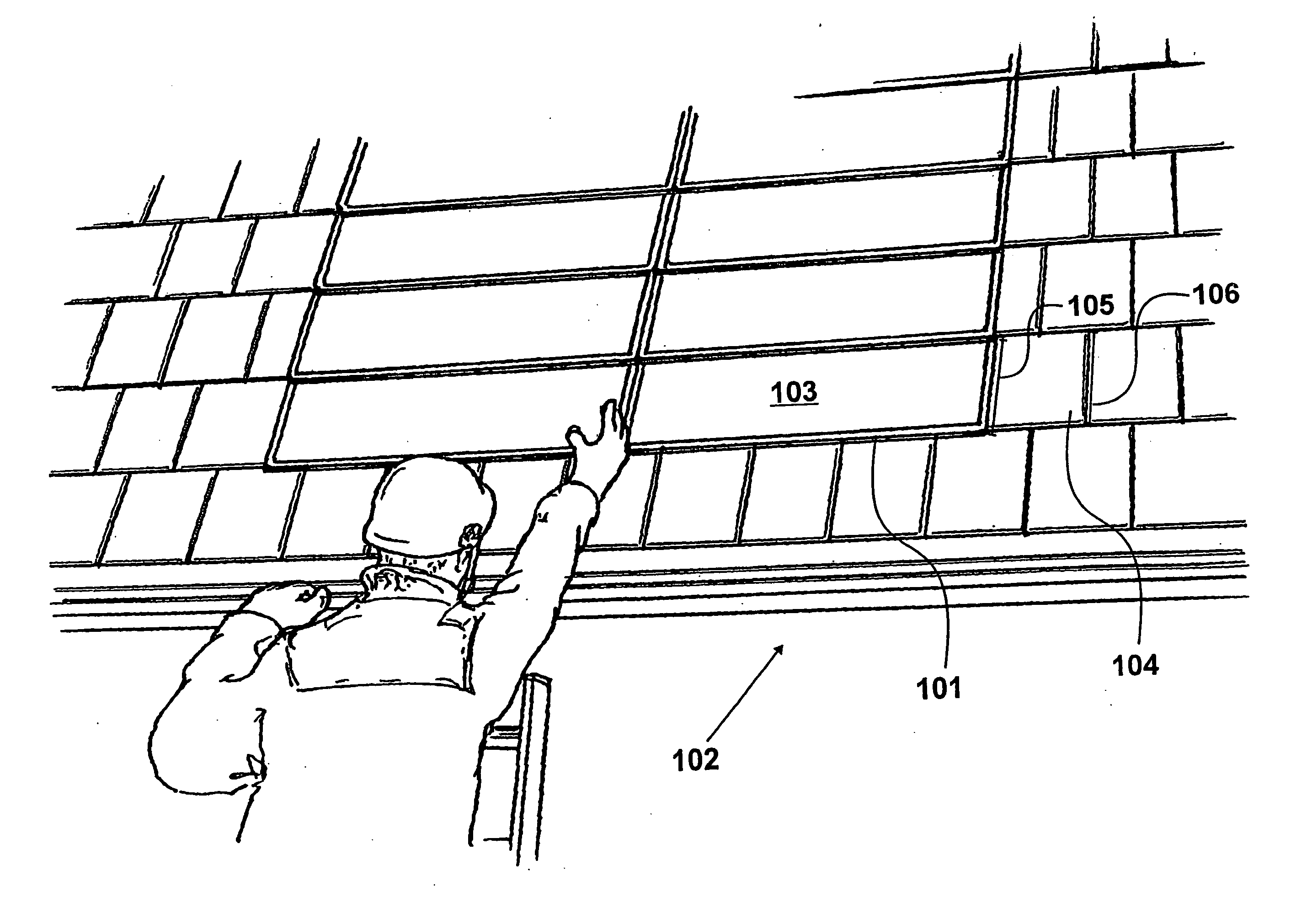
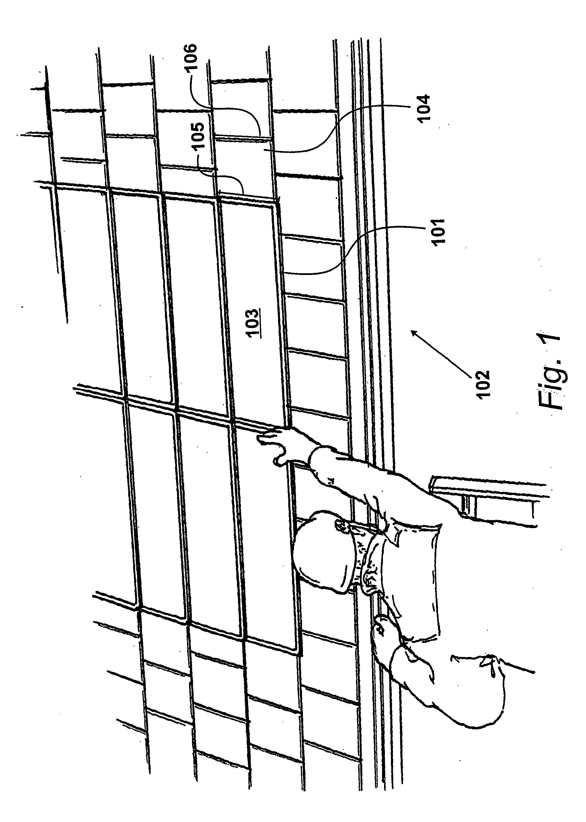
[0024]FIG. 1 shows a substantially planar solar energy collection device supported on a roof by support apparatus. Support apparatus 101 is shown fitted on roof 102. The support apparatus is configured to provide a frame surrounding a substantially planar solar energy collection device 103. The roof structure comprises a plurality of roof battens (not shown in this Figure) and a plurality of substantially flat roof elements, such as roof element 104. In this example, substantially planar solar energy collection device 103 is a photo-voltaic device but in alternative applications the solar energy collection device may be an alternative type of device.

[0025]The substantially flat roof elements may be any suitable roofing materials. In an application, the substantially flat roof elements are slates, which may be cut from natural slate or fabricated from slate-like material such as fibre cements. In an application, the substantially flat roof elements have the approximate dimensio...


PUM


Abstract

Apparatus for, and a method of, supporting a substantially planar solar energy collection device on a roof, the roof comprising a plurality of roof battens and a plurality of substantially flat roof elements. A back portion comprises a flange for locating the back portion on a roof batten. A front portion is configured to receive an edge of a solar energy collection device and defines a plurality of apertures in a front perimeter wall. First and second side portions are configured to extend from the back portion and to be releasably secured to the front portion. The apparatus is configurable to provide a frame for surrounding a solar energy collection device. The frame is securable to the roof by securing the back portion to a roof batten. The front portion is releasable from the first and second side portions when the frame is secured to a roof batten.

Description

CROSS REFERENCE TO RELATED APPLICATIONS[0001]This application claims priority from United Kingdom Patent Application No. 07 16 079.9, filed 17 Aug. 2007, the whole contents of which are incorporated herein by reference in their entirety.BACKGROUND OF THE INVENTION[0002]1. Field of the Invention[0003]The present invention relates to apparatus for, and a method of, supporting a substantially planar solar energy collection device on a roof, the roof comprising a plurality of roof battens and a plurality of substantially flat roof elements.[0004]2. Description of the Related Art[0005]It is known to provide a roof structure with a solar energy collecting panel. In some applications, the solar energy collecting panel is mounted upon a roof structure covering. In other applications, the solar energy collecting panel is mounted as part of a roof structure covering.[0006]Some roof elements are substantially flat, such as slate roof tiles. It is desirable to provide a roof comprising a plural...

Claims


Application Information

Patent Timeline
IPC IPC(8): H01L31/042
CPCF24J2/045F24J2/5211F24J2/5245F24J2/5256H02S20/23Y02B10/12Y02B10/20Y02E10/44Y02E10/47F24J2/5262F24S20/67F24S25/20F24S25/61F24S25/634F24S25/67Y02A30/60Y02B10/10Y02E10/50F24S25/00H02S20/00
Inventor KIMBERLEY, MALCOLM JOHN
Owner SOLAR CENTURY HLDG
Why Eureka
Eureka Blog
Learn More