
Adjustable dumbbell system

a dumbbell system and adjustable technology, applied in the field of adjustable dumbbell systems, to achieve the effects of low manufacturing cost, convenient and efficient manufacture and marketing, and durable and reliable construction

Active Publication Date: 2009-02-12
LIU PING
View PDF10 Cites 53 Cited by
  • Summary
  • Abstract
  • Description
  • Claims
  • Application Information

AI Technical Summary

Benefits of technology

[0014]The safety lock when in the raised locked orientation positions the axial projection in a space between adjacent fingers of the dowel disk for allowing only limited rotation of the dowel disk, cam bits, handle and adjustment disks with respect to the side covers, safety lock and grip. In this manner, the user may not change the weight to be lifted with the lifting of the dumbbell. The safety lock when in the lowered unlocked orientation positions the axial projection radially spaced from the fingers and spaces of the dowel disk for allowing full rotation between the dowel disk, cam bits, handle and adjustment disks with respect to the side covers, safety lock and grip. In this manner, the user may change the weight to be lifted with the lifting of the dumbbell.
[0019]It is another object of the present invention to provide a new and improved adjustable dumbbell system which may be easily and efficiently manufactured and marketed.
[0020]It is further object of the present invention to provide a new and improved adjustable dumbbell system which is of durable and reliable constructions.
[0021]An even further object of the present invention is to provide a new and improved adjustable dumbbell system which is susceptible of a low cost of manufacture with regard to both materials and labor, and which accordingly is then susceptible of low prices of sale to the consuming public, thereby making such adjustable dumbbell system economically available to the buying public.
[0022]Even still another object of the present invention is to provide an adjustable dumbbell system for selectively varying the weight to be lifted by a user, such selective varying being done in a safe, convenient and economical manner.

Problems solved by technology

While these devices fulfill their respective, particular objectives and requirements, the aforementioned patents do not describe an adjustable dumbbell system that allows for selectively varying the weight to be lifted by a user, such selective varying being done in a safe, convenient and economical manner.

Method used


Image

  • Adjustable dumbbell system
  • Adjustable dumbbell system
  • Adjustable dumbbell system

Examples


Embodiment Construction

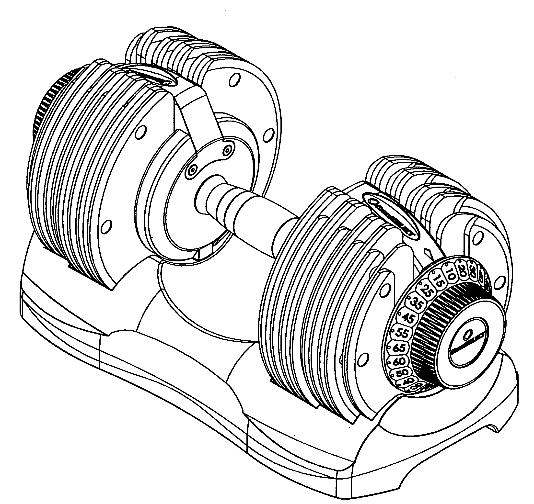
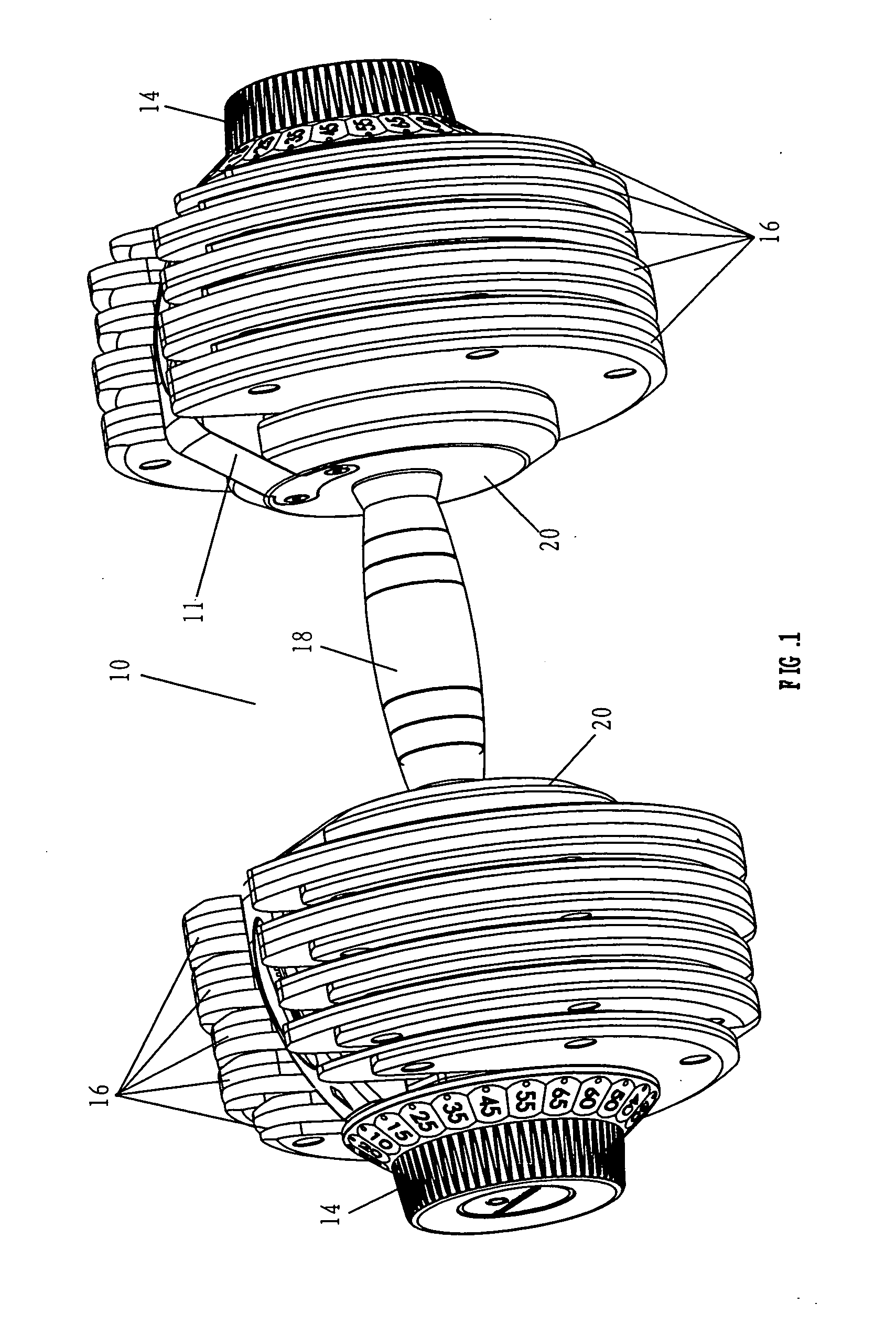
[0077]With reference now to the drawings, and in particular to FIG. 1 thereof, the preferred embodiment of the new and improved adjustable dumbbell system embodying the principles and concepts of the present invention and generally designated by the reference numeral 10 will be described.

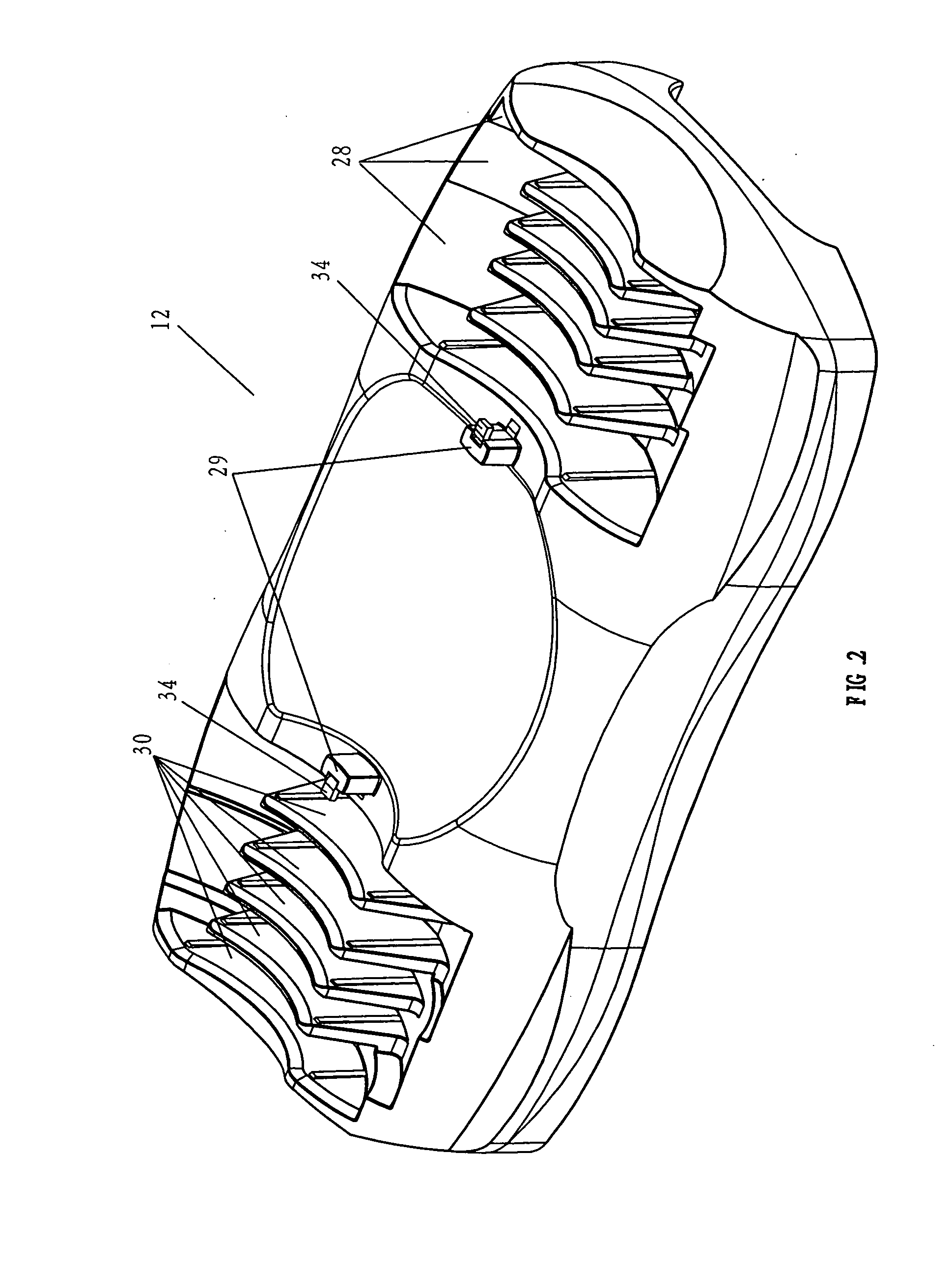
[0078]From a broad standpoint, the present invention is a dumbbell can realize different weight choices on a single piece of rod. The dumbbell is characterized in that the dumbbell can regulate the capacities of different weights. In other words, the dumbbell can randomly regulate one pair of dumbbell handwheels to the mark of the scheduled weight when the dumbbell is positioned on a dumbbell tray. A double safety locks system is provided and realizes the following two effects: when the dumbbell is positioned on the dumbbell tray, the dumbbell handwheels can realize choosing of gears of different weights by undergoing rotation of 360 degrees to the most. When, however, the dumbbell is positioned bet...


PUM


Abstract

A handle has opposed ends and a central extent. A grip rotationally receives the central extent of the handle. An adjustment wheel is secured to each end of the handle. A side cover is fixedly secured to each end of the grip. A dowel disk is on the handle adjacent to one side cover with fingers and spaces. A plurality of cam bits are supported on the handle. A safety lock is within the side cover adjacent to the dowel disk. The safety lock has a first end extent and a second end extent with a radial recess and a central extent with an axial projection. A coil spring within the radial recess urges the safety lock radially outwardly.

Description

RELATED APPLICATIONS[0001]This U.S. patent application is a continuation-in-part of U.S. patent application Ser. No. 11 / 900,852 filed Sep. 13, 2007 which is a continuation-in-part of U.S. patent application Ser. No. 11 / 494,248 filed Jul. 27, 2006 and issued Oct. 23, 2007 as U.S. Pat. No. 7,285,078, the subject matter of which applications is incorporated herein by reference.BACKGROUND OF THE INVENTION[0002]1. Field of the Invention[0003]The present invention relates to an adjustable dumbbell system and more particularly pertains to selectively varying the weight to be lifted by a user, such selective varying being done in a safe, convenient and economical manner.[0004]2. Description of the Prior Art[0005]The use of exercise weight systems of known designs and configurations is known in the prior art. More specifically, exercise weight systems of known designs and configurations previously devised and utilized for the purpose of varying weight through known methods and apparatuses ar...

Claims


Application Information

Patent Timeline
Patent Type & Authority Applications(United States)
IPC IPC(8): A63B21/075
CPCA63B21/00065A63B21/075A63B21/0728
Inventor LIU, PING
Owner LIU PING
Learn More