
Dual frequency doppler ultrasound probe

a doppler ultrasound and dual frequency technology, applied in the field of ultrasonic probes, can solve the problems of not providing any no velocity information, currently available ultrasound probes operate at only a single frequency,

Inactive Publication Date: 2009-02-05
UNETIXS VASCULAR INC
View PDF11 Cites 27 Cited by
  • Summary
  • Abstract
  • Description
  • Claims
  • Application Information

AI Technical Summary

Benefits of technology

[0005]It is also of note that in the prior art, Doppler imaging is done using different acoustical frequencies, where the selection of acoustical frequency is a compromise between resolution and the ability to perceive the internal structure being imaged. This compromise is based generally on the fact that while higher frequency Doppler waves provide higher resolution they do not penetrate into the body as deeply, lower frequencies penetrate more deeply but the penetration depth is achieved at the expense of resolution. A processor is then employed to receive the electrical signals from the Doppler probe and operate upon them to determine the information that is to be provided to the user on the display. In some systems, the processor generates an electrical signal that is converted and translated in the probe as an acoustic signal, while in other systems the probe itself generates the signal to be transmitted. Similarly, in some systems, the probe simply converts the received acoustic signal to an electrical signal that is transferred to the processor while in others, the probe processes the electrical form of received acoustic signal so that it at a different (lower) frequency and then provides the converted data to the processor.
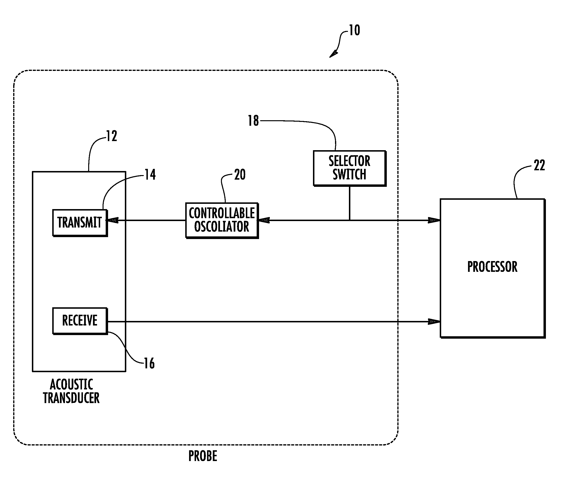
[0008]In one embodiment the probe of the present invention includes an acoustic transducer, a receiver and an operator control switch to selectively to select the frequency of operation from either of two predetermined frequencies and to show which frequency of operation is being used.

Problems solved by technology

In all of these technologies, however, the images produced show only the direction of flow and do not provide any no velocity information.
The difficulty that is encountered in the prior art is that the currently available ultrasound probes operate at only a single frequency.

Method used


Image

  • Dual frequency doppler ultrasound probe
  • Dual frequency doppler ultrasound probe
  • Dual frequency doppler ultrasound probe

Examples


Embodiment Construction

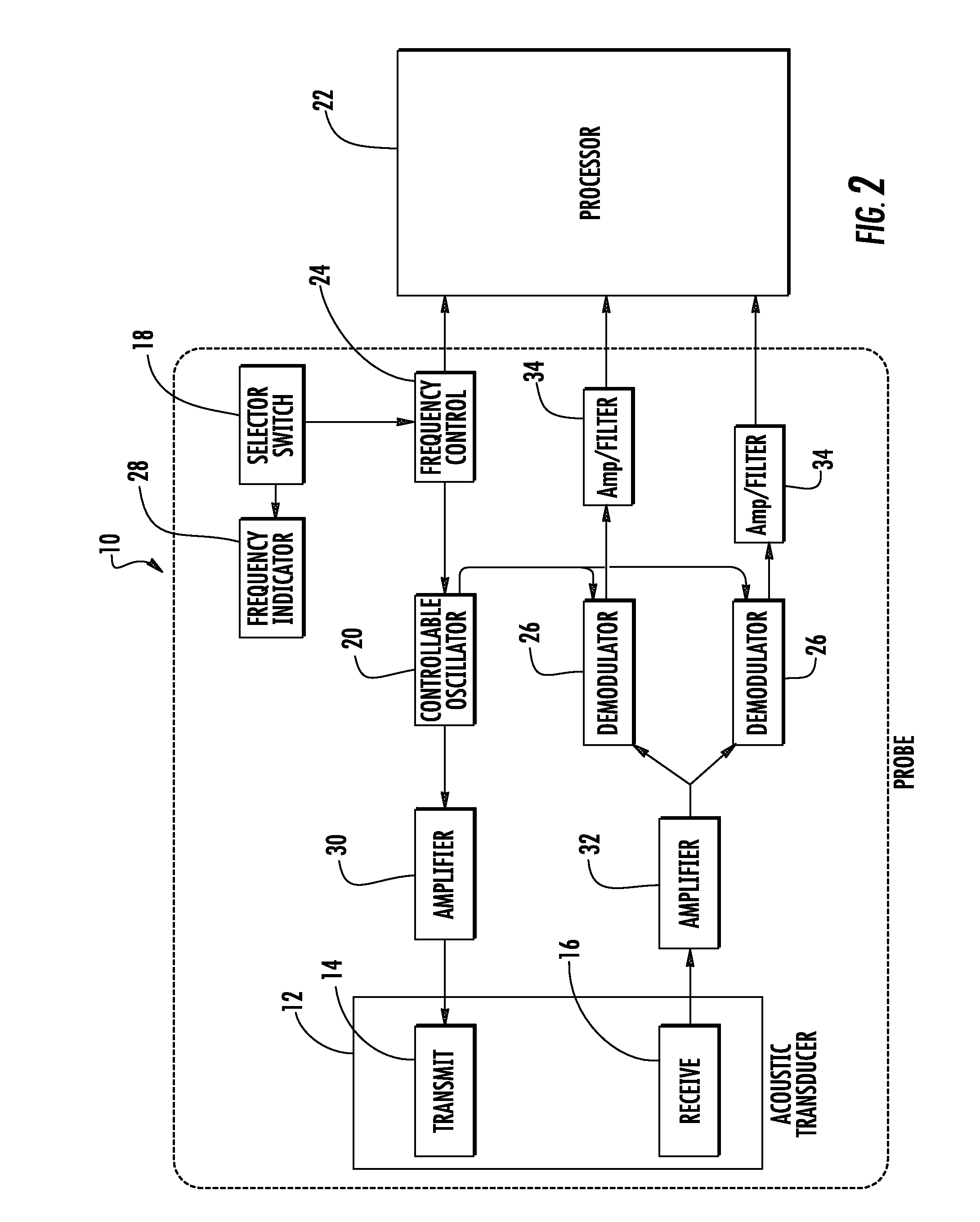
[0022]Now referring to the drawings, a schematic depiction of the ultrasonic probe of the present invention is shown and generally illustrated at 10 in FIG. 1. As was stated above, the present invention is directed at providing an ultrasonic probe 10 that is selectively operable over at least two different frequencies, thereby allowing an operator to conduct an ultrasonic examination across differing ultrasonic frequencies without having to change probes. In this regard, in a preferred embodiment the probe 10 of the present invention generally includes an acoustic transducer 12 having a transmit section 14 that creates and transmits an acoustic signal from a high frequency electrical signal and a receive section 16 that receives a reflection of the transmitted acoustic signal and converts the received reflection into an electrical signal. Further, the probe 10 includes a selection switch 18 that allows the user to selectively determine a frequency at which the acoustic signal is tra...


PUM


Abstract

An ultrasonic Doppler probe is provided for use in connection with non-invasive Doppler imaging of fluid flow within the human body. The Doppler probe can be selectively operated at more than one frequency during the course of a Doppler imaging examination thereby enhancing the resolution of the image obtained while also increasing the effective depth of the image. The probe of the present invention employs piezo-electric materials for the formation of acoustic transmitting and receiving transducers that are positioned within the probe to allow the probe to be selectively operated at a number of different frequencies spanning no more than one octave in frequency range.

Description

CROSS-REFERENCE TO RELATED APPLICATIONS[0001]This application is related to and claims priority from earlier filed U.S. Provisional Patent Application No. 60 / 953,014, filed Jul. 31, 2007.BACKGROUND OF THE INVENTION[0002]The present invention relates generally to an ultrasonic probe for non-invasive measurement of fluid flow within the human body. More specifically, the present invention relates to an ultrasonic Doppler probe for measuring fluid flow within the human body that incorporates a dual frequency acoustical transducer, thereby allowing operation of the probe at both higher and lower frequencies without the need for the operator to change probes.[0003]As ultrasonic technology has improved, non-invasive ultrasonic diagnostic equipment has become an indispensable tool for clinical use. For many years, real-time B-mode ultrasound imagers have been used in connection with the investigation and imaging of stationary soft tissue structures within the human body. In addition, the m...

Claims


Application Information

Patent Timeline
Patent Type & Authority Applications(United States)
IPC IPC(8): A61B8/00
CPCA61B8/4472A61B8/06
Inventor COHEN, MARTIN L.HAEFELE, JOHNCASTILLO, ANTHONY
Owner UNETIXS VASCULAR INC
Learn More