Transmission ratio variable device and steering gear

Inactive Publication Date: 2009-02-05
JTEKT CORP
View PDF3 Cites 7 Cited by
  • Summary
  • Abstract
  • Description
  • Claims
  • Application Information

AI Technical Summary

Benefits of technology

[0010]To solve the above problem, it is an object of the present invention to provide a variable transmission ratio apparatus that effectively prevents the ratcheting phenomenon from occurring between a flexible spline and a circular spline when a steering operation is performed in a locked state.
[0012]When a steering operation is performed in a locked state, the circular spline connected to the output shaft rotates in a direction opposite the direction in which the wave generator rotates. However, reaction torque countering the steering torque, that is, torque acting in the same direction as the rotation direction of the wave generator, is input into the circular spline. Thus, each external tooth of the flexible spline is displaced in a direction in which it moves away from the space between adjacent internal teeth of the circular spline, or in a radially inward direction, while its side surface slides along side surfaces of the internal teeth of the circular spline. As a result, friction produced when the external teeth of the flexible spline moves away from the internal teeth of the circular spline pulls the flexible spline in the radially inward direction. This effectively prevents ratcheting from occurring between the flexible spline and the circular spline when a steering operation is performed in a locked state.
[0014]When the circular spline connected to the output shaft has a large number of teeth, the apparatus may have the problem of ratcheting when a large inverse input load is applied, such as when a steered wheel crashes against a curb. Although such an inverse input load becomes instantaneously extremely high, the inverse input load is continuously applied for a very short period of time. Such a problem can be solved by increasing the rigidity of the circular spline. When the above structure increases the rigidity of the circular spline connected to the output shaft and effectively prevents ratcheting when an inverse input load is applied.

Problems solved by technology

However, this does not stop operation of the strain wave gear mechanism.
When a large torque is applied to the mated portions of the flexible spline and the circular splines, the tooth of the flexible spline and the teeth of the circular splines may not be properly mated with each other, that is a certain tooth goes over the corresponding tooth to be mated with.
This phenomenon is referred to as “ratcheting.” In the locked state, the rotating mated portions of the flexible spline and the circular splines may cause problems unique to the housing-fixed variable transmission ratio apparatus.

Method used


Image

  • Transmission ratio variable device and steering gear
  • Transmission ratio variable device and steering gear
  • Transmission ratio variable device and steering gear

Examples


first embodiment

[0021]A variable transmission ratio apparatus of a housing-fixed type according to a first embodiment of the present invention will now be described with reference to the drawings.

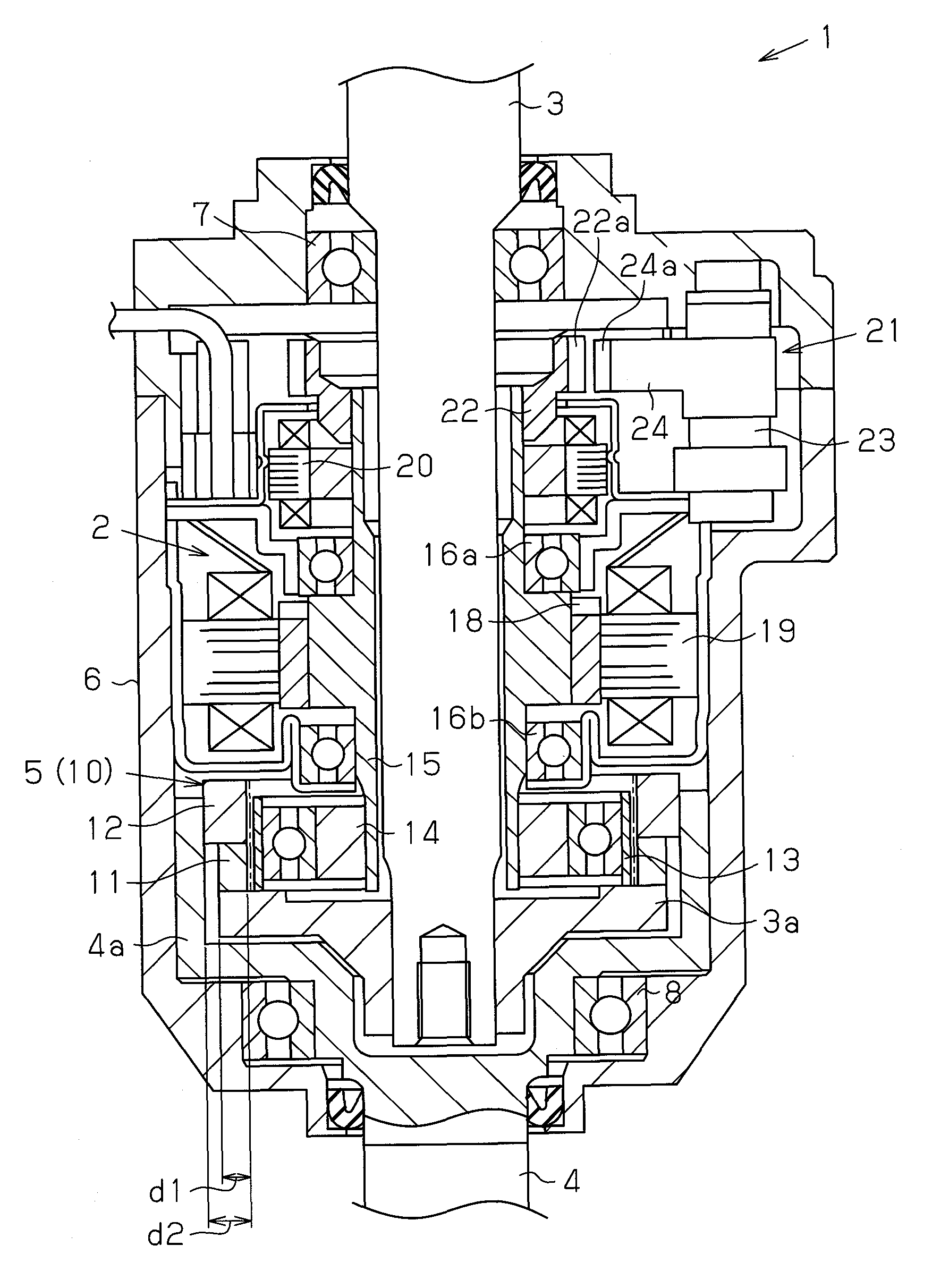
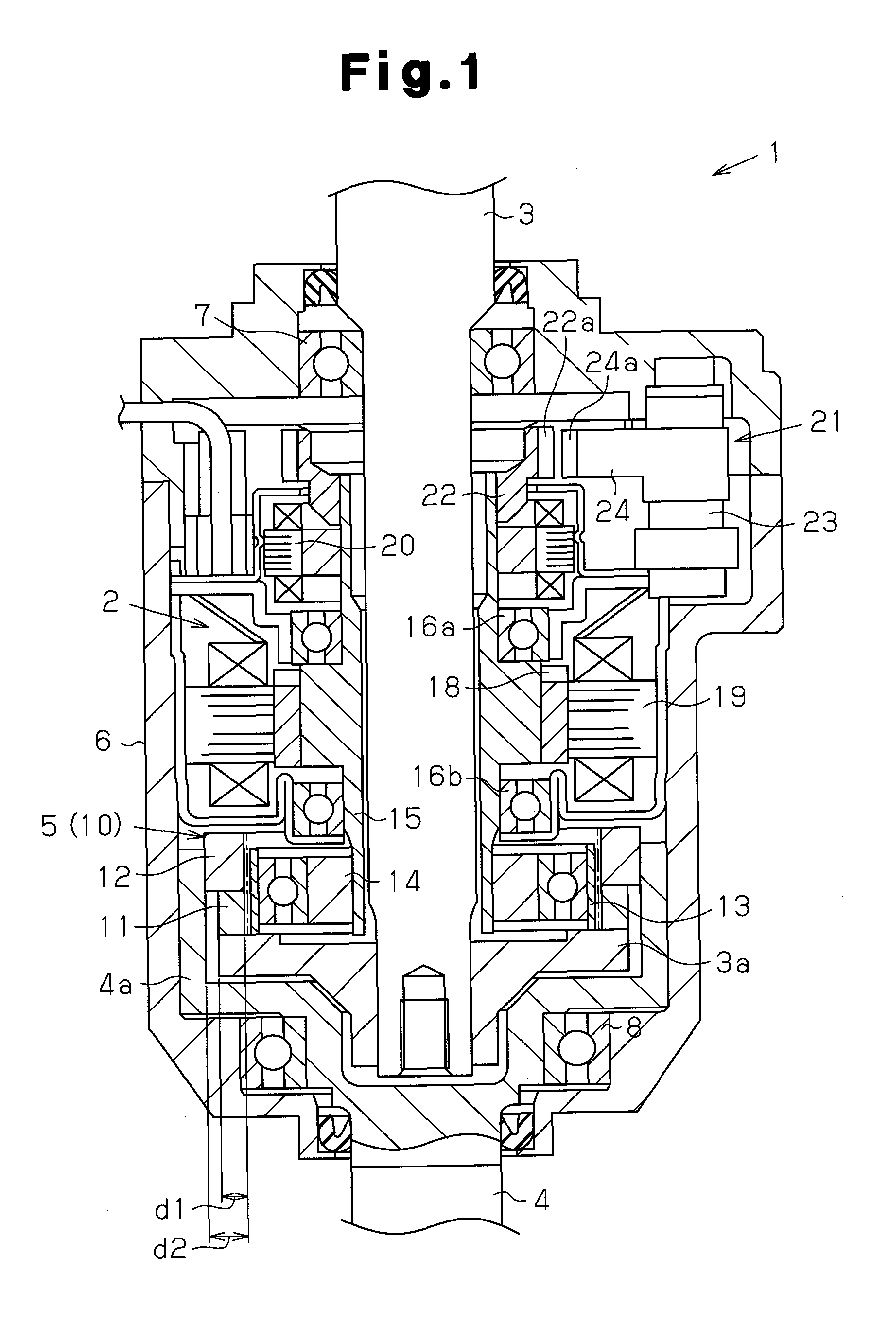
[0022]As shown in FIG. 1, a variable transmission ratio apparatus 1 includes a motor 2, a differential gear mechanism 5, and a housing 6. The motor 2 serves as a power source. The differential gear mechanism 5 adds rotation resulting from motor drive to rotation from an input shaft 3 resulting from a steering operation and transmits the resulting rotation from the input shaft 3 to an output shaft 4. The housing 6 accommodates the motor 2 and the differential gear mechanism 5.

[0023]In detail, the housing 6 of the present embodiment is cylindrical. The input shaft 3 and the output shaft 4 have end portions that are arranged in the housing 6 and supported in a rotatable manner relative to the housing 6 by bearings 7 and 8 arranged in the vicinity of two open ends of the housing 6. More specifically, the input...

second embodiment

[0042]A second embodiment of the present invention will now be described in detail with reference to the drawings.

[0043]As shown in FIG. 3, a vehicle steering apparatus of the present embodiment includes a transmission shaft 60 forming part of a steering shaft 53 to which a steering wheel 52 is fixed. The transmission shaft 60 is connected to a rack shaft 55 by a rack and pinion mechanism 54. Rotation of the steering shaft 53 resulting from a steering operation is converted to a reciprocal linear movement of the rack shaft 55 by the rack and pinion mechanism 54.

[0044]Pinion teeth 60a formed on a lower end of the transmission shaft 60 are mated with rack teeth 55a formed on the rack shaft 55. The reciprocal linear movement of the rack shaft 55 caused by rotation of the steering shaft 53 is transmitted to knuckles (not shown) by tie-rods connected to the two ends of the rack shaft 55. This changes the steering angle of steered wheels of a vehicle, that is, the driving direction of the...


PUM


Abstract

A variable transmission ratio apparatus for effectively preventing ratcheting between a flexible spline and a circular spline caused by a steering operation performing in a locked state. A variable transmission ratio apparatus includes a strain wave gear mechanism for adding rotation resulting from motor drive to rotation from an input shaft resulting from a steering operation and transmitting the added rotation to an output shaft, a housing accommodating the strain wave gear mechanism and the motor and fixed to a non-rotating portion, and a lock device for locking the housing and a motor shaft in a manner prohibiting relative rotation therebetween. Among the circular splines forming the strain wave gear mechanism, the number of teeth of the circular spline connected to the output shaft is greater than the number of teeth of the circular spline connected to the input shaft.

Description

TECHNICAL FIELD[0001]The present invention relates to a variable transmission ratio apparatus and a steering apparatus using a strain wave gear mechanism.BACKGROUND ART[0002]In the prior art, a variable transmission ratio apparatus using a strain wave gear mechanism as a differential gear mechanism adds rotation resulting from motor drive to rotation from an input shaft resulting from a steering operation and transmits the resulting rotation from the input shaft to an output shaft. Such a variable transmission ratio apparatus may be of a housing-integrated type in which a housing rotates integrally with an input shaft (refer, for example, to patent document 1 below), or may be of a housing-fixed type in which a housing is fixed to a non-rotating portion of a vehicle (refer, for example, to patent document 2 below).[0003]The strain wave gear mechanism may include, for example, a pair of circular splines, with one of the circular splines having a greater number of teeth than the flexi...

Claims


Application Information

Patent Timeline
IPC IPC(8): B62D5/04F16H48/12
CPCB62D5/008F16H35/008Y10T74/19005F16H49/001Y10T74/19F16H48/12
Inventor YAMAMORI, MOTOYASUFUJIWARA, HIDETOSHIWATANABE, OSAMUSUZUKI, YOSHINORISUZUKI, HIROTSUNE
Owner JTEKT CORP
Why Eureka
Try Eureka