
Method of Making a Marine Gas Turbine Filter

a gas turbine filter and marine technology, applied in the direction of filtration separation, other chemical processes, separation processes, etc., can solve the problems of reducing the efficiency of filtration, expensive construction techniques, and laborious

Active Publication Date: 2009-02-05
AAF MCQUAY INC
View PDF13 Cites 27 Cited by
  • Summary
  • Abstract
  • Description
  • Claims
  • Application Information

AI Technical Summary

Benefits of technology

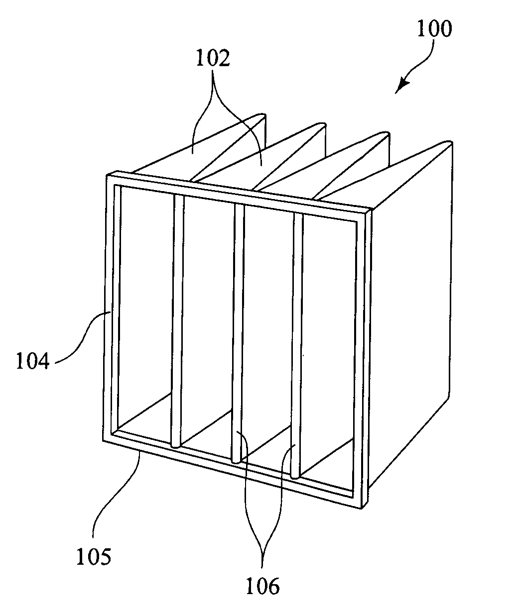
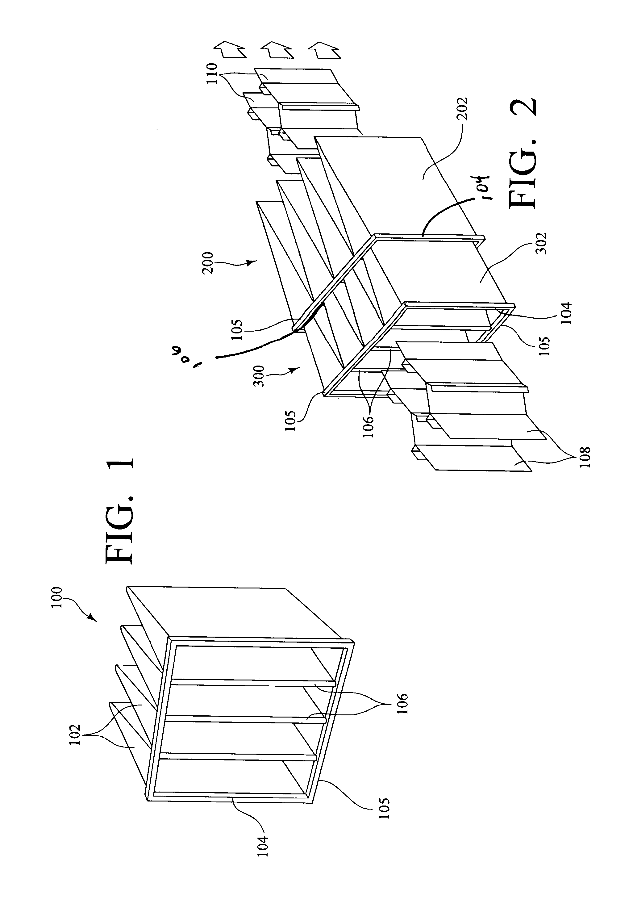
[0007]The present invention provides a method for making a pocket filter assembly having a header with at least one aperture wherein the inlet perimeter of a filter element is unitary with the header. Advantageously, the header has a pair of opposing side elements and a pair of end elements forming a rectangular header having a continuous channel in a downstream side thereof for receiving an upstream edge of pocket filter media. The channel having the filter media placed therein is filled with a liquid polymeric material, advantageously polyurethane, that is solidified making the filter media and header unitary. This provides a secure anchor and an air and water tight mounting for the filter media. The invention may be applied to filters wherein individual pocket filter elements are secured to the header or advantageously a continuous sheet of filter media having adjacent pocket filter elements formed therein with seams at outer edges. The method of the present invention provides a filter assembly of the extended area type wherein the open ends of elongated flexible pocket elements are unitary with a header.

Problems solved by technology

Such construction techniques have been found to be expensive and labor intensive.
Additionally, air, gas or water being filtered often times leaks about the filter pocket interface with the header, greatly reducing the efficiency of filtration.

Method used


Image

  • Method of Making a Marine Gas Turbine Filter
  • Method of Making a Marine Gas Turbine Filter
  • Method of Making a Marine Gas Turbine Filter

Examples


Embodiment Construction

)

[0014]It is to be understood that the invention is not limited in its application to the details of construction and the arrangement of components set forth in the following description or illustrated in the drawings. The invention is capable of other embodiments and of being practiced or of being carried out in various ways. Also, it is to be understood that the phraseology and terminology used herein is for the purpose of description and should not be regarded as limiting. The use of “including,”“comprising,” or “having” and variations thereof herein is meant to encompass the items listed thereafter and equivalents thereof as well as additional items. Unless limited otherwise, the terms “connected,”“coupled,”“in communication with” and “mounted,” and variations thereof herein are used broadly and encompass direct and indirect connections, couplings, and mountings. In addition, the terms “connected” and “coupled” and variations thereof are not restricted to physical or mechanical ...


PUM

PropertyMeasurementUnit
Angleaaaaaaaaaa
Perimeteraaaaaaaaaa

Abstract

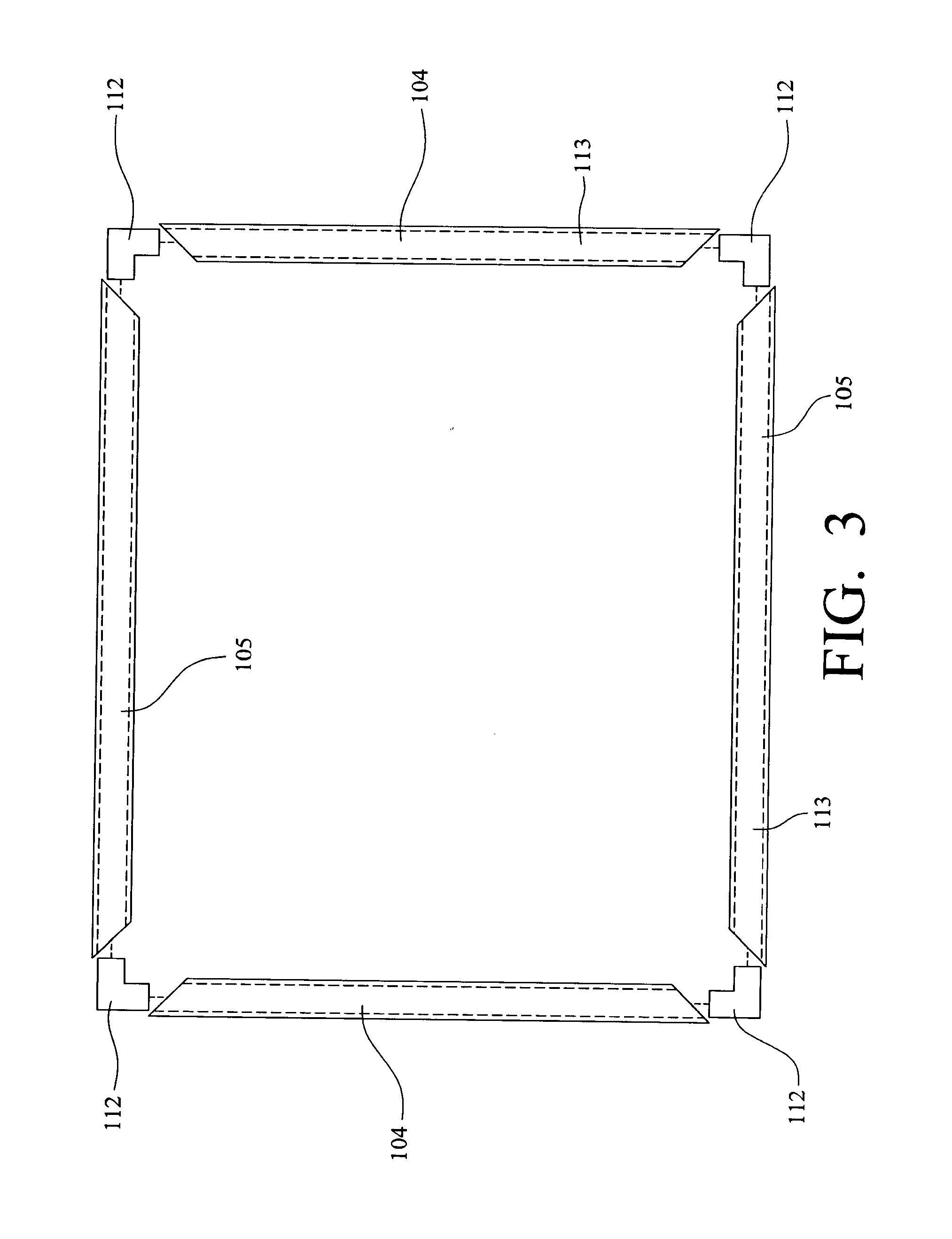
A method for making a pocket filter assembly is provided. Two side and two end header elements each having a pair of longitudinally extending side walls and a longitudinally extending bottom wall forming a longitudinally extending channel are joined at ends forming a rectangular header with two opposing sides and two opposing ends. The bottom wall and side walls of each of the opposing sides and the bottom walls and said side walls of each of said opposing ends become adjacent forming a rectangular header with a continuous bottom wall and continuous inner and outer side wall having a continuous channel therein. An upstream perimeter portion of a pocket filter element is inserted in the continuous channel and a liquid polymeric material is placed therein. The polymeric material is solidified forming a header frame having the upstream perimeter portion of the filter element unitary therewith.

Description

[0001]This application claims priority to U.S. Provisional 60 / 953,088, filed Jul. 31, 2007, the entire contents of which are incorporated herein.BACKGROUND OF THE INVENTION[0002]1. Field of the Invention[0003]The present invention relates generally to air or gas filter assemblies having pocket shaped filter bags extending from a header.[0004]2. Description of the Related Art[0005]Air and gas cleaning filter assemblies of the type wherein a plurality of elongated tubular flexible filter bags in the form of pockets or bags having open ends attached to a header about apertures in the header is known. The configuration of the pockets causes them to expand by air pressure and extend downstream away from the header in the direction of air flow when in use. This expansion and extension provides increased filter area for a given header area.[0006]In the prior art, these filter elements are typically mechanically attached to the header with clips, rivets, clamps, fasteners, adhesive, to a st...

Claims


Application Information

Patent Timeline
IPC IPC(8): B01D46/00B29C47/00
CPCB01D46/0005B01D46/02B01D46/023B01D2271/025Y10T156/1069Y10S264/48Y10T156/1064Y10T156/1062Y10T156/1066Y10S55/05
Inventor LANGLANDS, DEREKFEKKES, WIM
Owner AAF MCQUAY INC
Learn More