Golf club shaft

Inactive Publication Date: 2009-01-29
SUMITOMO RUBBER IND LTD
View PDF3 Cites 24 Cited by
  • Summary
  • Abstract
  • Description
  • Claims
  • Application Information

AI Technical Summary

Benefits of technology

[0025]The present invention has been made in view of the above-described problems. Therefore it is an object of the present invention to provide a lightweight golf club shaft (hereinafter often referred to as merely shaft) capable of hitting a golf ball a long distance and improving the directional property thereof by allowing an improved crushing strength of a hoop layer to serve for the improvement of the head speed of the golf club shaft.

Problems solved by technology

Because there is the rule for restricting the flight performance of the golf club head, the golf club head has a limit in the design of enhancing the flight performance.
Consequently the sectional configuration of the shaft is liable to become elliptic.
Thus when the cylindrical body is used as a golf club shaft, it has an insufficient durability and a bad directional property.
Because the reinforcing fibers of the hoop layer are disposed in the circumferential direction of the cylindrical body, the end of the hoop layer is liable to have a defective adhesion to an adjacent inner layer in a step of winding the prepreg forming the hoop layer.
In addition, when the outermost layer is composed of the hoop layer, the cylindrical body is liable to have a poor outlook, and further a defective air accumulation is generated in a molded end product, which may lead to deterioration of durability.
But this construction does not allow the improvement of the crushing rigidity of the hoop layer to serve for the improvement of the head speed.
Thus even though the crushing rigidity at the grip-side butt is enhanced, the effect of improving the head speed cannot be expected.
But no technical ideas nor constructions allowing the property of the crushing rigidity improved by the hoop layer to serve for the improvement of the head speed are disclosed.

Method used


Image

  • Golf club shaft
  • Golf club shaft
  • Golf club shaft

Examples


example 1

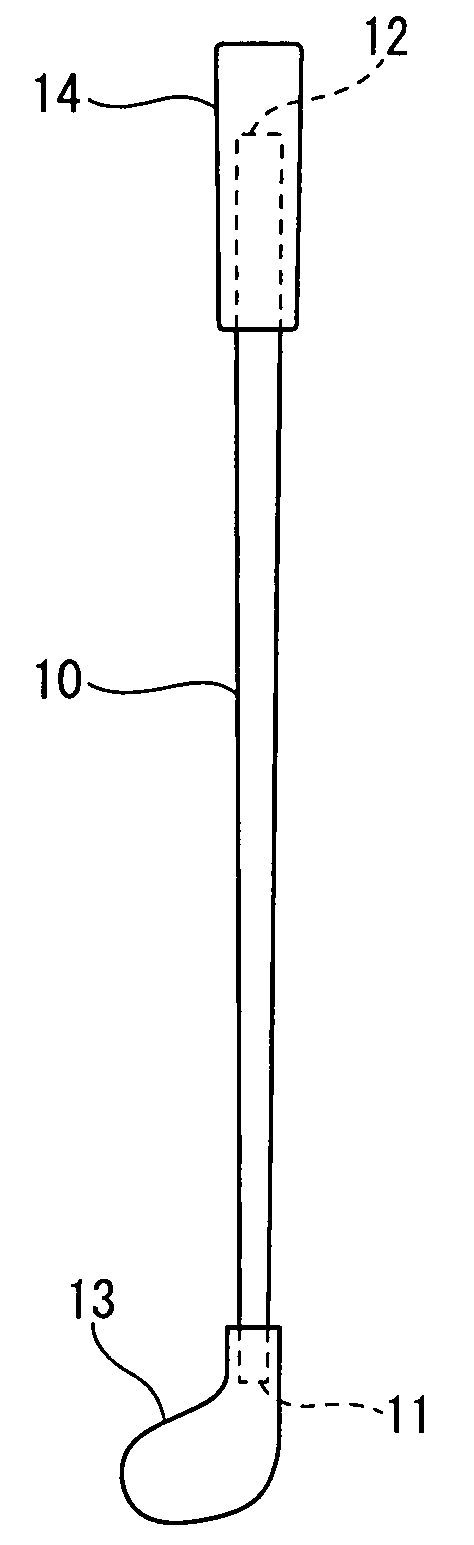
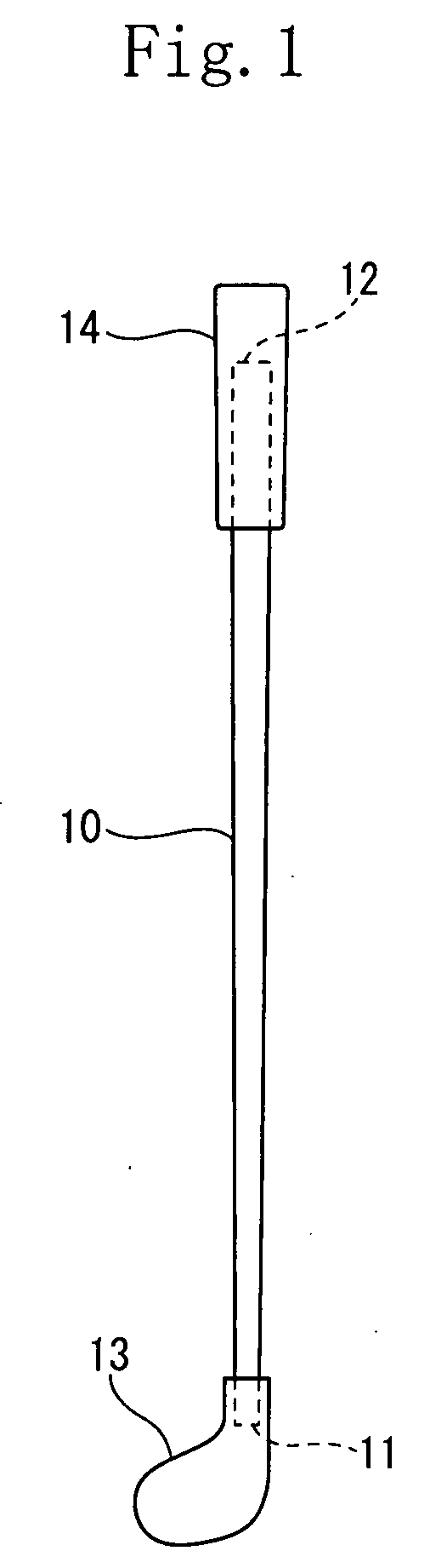
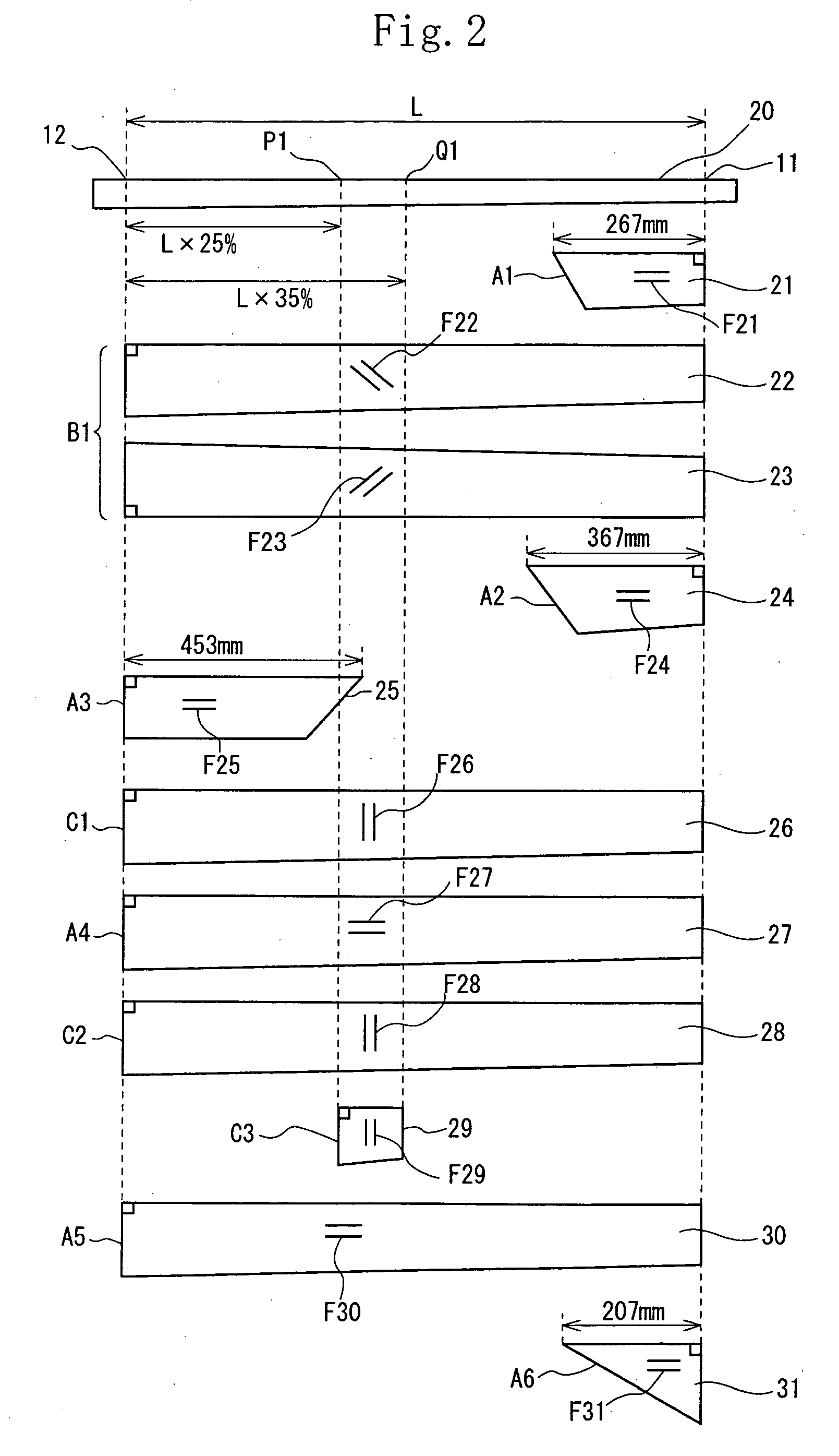
[0103]A prepreg having a fiber orientation angle of 90° was wound in a range from a point P1 spaced at 25% of the full length L of the shaft 10 from the grip-side butt 12 thereof to a point Q1 spaced at 35% of the full length L of the shaft 10 from the grip-side butt 12 thereof to form a partial reinforcing hoop layer C3. The ninth-layer prepreg composed of a product produced by Graphite Fiber Co., Ltd. had a fiber modulus of elasticity in tension of 73.5 t / mm2 and a thickness of 0.04 mm. The prepreg had a reference number of “E7026A-03S” (carbon fiber reference number: “YSH-70”).

example 2

[0104]The shaft of the example 2 was the same as that of the example 1 in that the ninth-layer prepreg from the innermost layer was composed of the partial reinforcing hoop layer C3, having a fiber orientation angle of 90°, which was disposed in the region from the point P1 to the point Q1. But the shaft of the example 2 was different from that of the example 1 in that the ninth-layer prepreg produced by Graphite Fiber Co., Ltd. had a modulus of elasticity in tension of 80.1 t / mm and a thickness of 0.07 mm. The prepreg had a reference number of “E8026A-07S” (carbon fiber reference number: “YS-80”).

example 3

[0105]As shown in FIG. 4, the shaft of the example was the same as that of the example 1 except that as shown in FIG. 4, the region where the partial reinforcing hoop layer C3 was disposed was in the range from a point P1 spaced at 25% of the full length L of the shaft 10 from the grip-side butt 12 thereof to a point Q2 spaced at 30% of the full length L of the shaft 10 from the grip-side butt 12 thereof.


PUM


Abstract

A golf club shaft (10) having a weight not less than 30 g nor more than 60 g. The golf club shaft (10) includes a bias layer (B1) composed of a prepreg whose reinforcing fibers have an orientation angle of not less than ±10° nor more than 80° to an axis of the golf club shaft (10) and a straight layers (A1 through A6) each composed of a prepreg whose reinforcing fibers have an orientation angle within 0°±10° to the axis of the golf club shaft (10). At least one partial reinforcing hoop layer whose reinforcing fibers have an orientation angle of within 90°±10° to the axis of the golf club shaft (10) is disposed in only an important reinforcing region in a range from a point (P) spaced at 15% of a full length (L) of the golf club shaft (10) from a grip-side butt (12) thereof to a point (Q) spaced at 45% of the full length (L) of the golf club shaft (10) from the grip-side butt (12) thereof.

Description

[0001]This nonprovisional application claims priority under 35 U.S.C. §119(a) on Patent Application No(s). 2007-190431 filed in Japan on Jul. 23, 2007, the entire contents of which are hereby incorporated by reference.[0002]1. Field of the Invention[0003]The present invention relates to a golf club shaft (hereinafter often referred to as merely shaft). More particularly, the present invention is intended to increase the head speed of a lightweight golf club shaft so that it has a high performance of hitting a golf ball a long distance.[0004]2. Description of the Related Art[0005]In recent years, to allow a golf club to hit a golf ball a long distance, the present tendency is to make the golf club shaft and the golf club head lightweight. Because there is the rule for restricting the flight performance of the golf club head, the golf club head has a limit in the design of enhancing the flight performance. Thus the shaft is demanded to have performance for hitting the golf ball a long...

Claims


Application Information

Patent Timeline
IPC IPC(8): A63B53/10A63B102/32
CPCA63B53/10A63B2209/02A63B59/0029A63B60/14
Inventor KUMAMOTO, TOMIO
Owner SUMITOMO RUBBER IND LTD
Why Eureka
Try Eureka