High screwing screw

a screw and screw technology, applied in the field of screw, can solve the problems of low screwing efficiency, lack of stable screwing capability, and lower screwing efficiency, so as to improve the cutting ability, increase the screwing efficiency, and improve the effect of screwing efficiency

Inactive Publication Date: 2009-01-29
ESSENCE METHOD REFINE
View PDF38 Cites 25 Cited by
  • Summary
  • Abstract
  • Description
  • Claims
  • Application Information

AI Technical Summary

Benefits of technology

[0009]The objects of the present invention are to provide a screw that aids in increasing the screwing efficiency by enhancing the cutting capability and maintaining a good resistance of extraction.

Problems solved by technology

1. Decreasing the Efficiency of Screwing
Thus, the screw 1 has lower resistance of extraction and also lacks of stable screwing capability.
However, it should also be adjusted depend on different objects while in operation, thus causing the inconvenience.

Method used


Image

  • High screwing screw
  • High screwing screw
  • High screwing screw

Examples


Embodiment Construction

[0030]Before the present invention is described in greater detail, it should be noted that the similar elements are denoted by the same reference numerals throughout the disclosure.

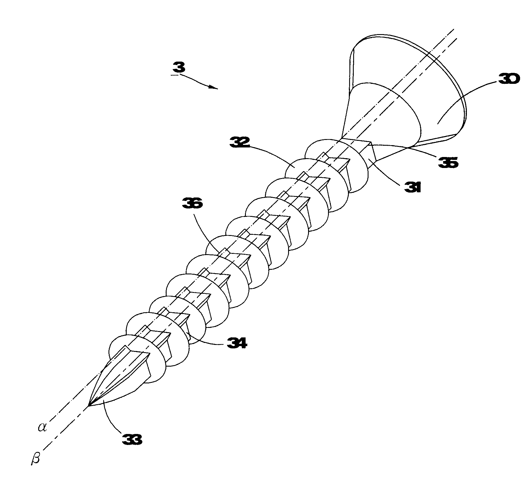
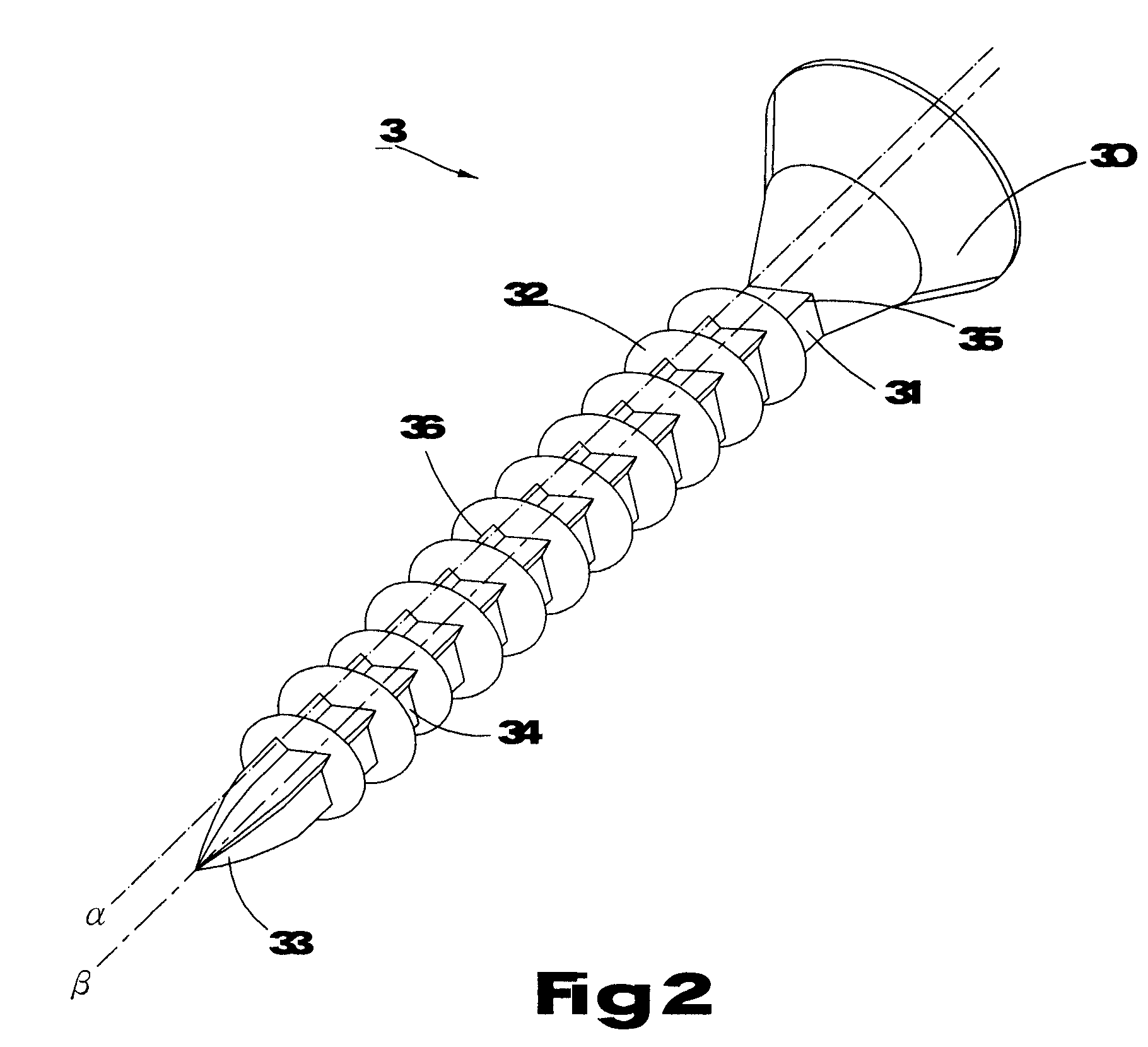
[0031]Referring to FIG. 2, a screw 3 of the first preferred embodiment comprises a screw head 30, a shank 31 longitudinally extending from the head 30, a plurality of threads 32 disposed helically along the shank 31, and a drilling portion 33 disposed on a distal end of the shank 31, opposite to the screw head 30; wherein, the shank 31 consists of a plurality of flat surfaces 34 densely disposed around an outer circumference thereof; additionally, the flat surfaces can be joined as a two-side shape shown in FIG. 3, or as a triangular shape shown in FIGS. 4 and 5, and the triangular shape is adopted in the preferred embodiments of the present invention.

[0032]Still further, referring to FIG. 2, a lip 35 is defined by the junction of any of two adjacent flat surfaces 34; a linking line “α” is defined by alig...


PUM

PropertyMeasurementUnit
circumferenceaaaaaaaaaa
shapeaaaaaaaaaa
angleaaaaaaaaaa

Abstract

The present invention pertains to a screw notably comprising a shank with a plurality of flat surfaces; wherein, a lip is defined by the junction of any of two adjacent flat surfaces, and a rib located between two threads is protruded from the lip. While in operation, by means of the configuration of the ribs, the screw facilitates to increase the cutting capability for achieving a higher screwing speed and preserve a good resistance of extraction.

Description

BACKGROUND OF THE INVENTION[0001]1. Field of the Invention[0002]The present invention relates to a screw, in particular a screw with a function of enhancing the capability of cutting, increasing the screwing efficiency and keeping a good resistance of extraction.[0003]2. Description of the Related Art[0004]Referring to FIG. 1, a conventional screw 1 comprises a head 10, a shank 11 extending from the head 10, a plurality of threads 12 disposed helically along the shank 11, and a drilling tip 13 disposed on the end of the shank 11. While in operation, the screw 1 can be screwed into the object 2 through the drilling tip 13 and the threads 12 for cutting the fibers of the object 2.[0005]However, there are still some disadvantages with the conventional screw 1:1. Decreasing the Efficiency of Screwing[0006]The fibers of the object 2 may not be entirely chipped by threads 12, which results in twining itself round the shank 11 and increasing the cutting resistance. As a consequence, the cu...

Claims


Application Information

Patent Timeline
Patent Type & Authority Applications(United States)
IPC IPC(8): F16B25/10
CPCF16B25/0015F16B25/0021F16B25/0057F16B25/10F16B25/0068F16B25/0073F16B25/0078F16B25/0063
Inventor CHANG, CHING-HSIANG
Owner ESSENCE METHOD REFINE
Why Eureka
Try Eureka