
Image forming apparatus having contactless type temperature sensor

a temperature sensor and image forming technology, applied in the field of image forming apparatus, can solve the problems of contactless type sensor, affecting the cost of consumables, and liable to appear as gloss, so as to improve the temperature detecting precision of temperature detecting sensor

Inactive Publication Date: 2009-01-29
CANON KK
View PDF3 Cites 11 Cited by
  • Summary
  • Abstract
  • Description
  • Claims
  • Application Information

AI Technical Summary

Benefits of technology

[0017]The invention is made in consideration of the foregoing problems and it is an object of the invention to provide an image forming apparatus which can improve temperature detecting precision of a temperature detecting sensor.
[0018]Another object of the invention is to provide an image forming apparatus in which the air is difficult to flow from a portion around a fixing unit into a temperature detecting opening portion provided for an outer casing of the fixing unit.

Problems solved by technology

However, if the contact type sensor is used, since surface states (temperature distribution and a consumption degree) of the fixing roller and the fixing belt, particularly, only regions which come into contact with the sensor change, such a change is liable to appear as a gloss variation on the image fixed onto the sheet.
Since micro toner foulings deposited onto the fixing roller and the fixing belt are accumulated into the contact type sensor, there is such a problem that when the accumulated fouling is suddenly peeled off, it is deposited onto the fixed image.
However, since the contactless type sensor is very expensive, if it is built in the fixing unit which is presumed to be exchanged as consumables, it directly exerts an influence on the costs of the consumables.
The over-temperature of the fixing unit becomes a cause of winding of a sheet or an over-gloss of the picture quality.
A temperature difference between the detection area and the other areas becomes a cause of the gloss variation of the fixed image.
Especially, in the construction in which the contactless type sensor is arranged under the fixing unit, an influence of the heat convection from the temperature detecting opening portion is liable to occur.
The problem of deterioration in temperature detecting precision appears further typically.
However, since transmittance of infrared rays of the window 145 made of the infrared transmitting material changes depending on the surface state, there is a risk that the detecting precision becomes unstable due to a factor such as variation among parts or deposition of the fouling.
Thus, there is also a risk that the temperature cannot be detected but an abnormality occurs in the heating control and, in the worst case, a temperature of the fixing unit exceeds a limit temperature and the fixing unit is broken.

Method used


Image

  • Image forming apparatus having contactless type temperature sensor
  • Image forming apparatus having contactless type temperature sensor
  • Image forming apparatus having contactless type temperature sensor

Examples


first embodiment

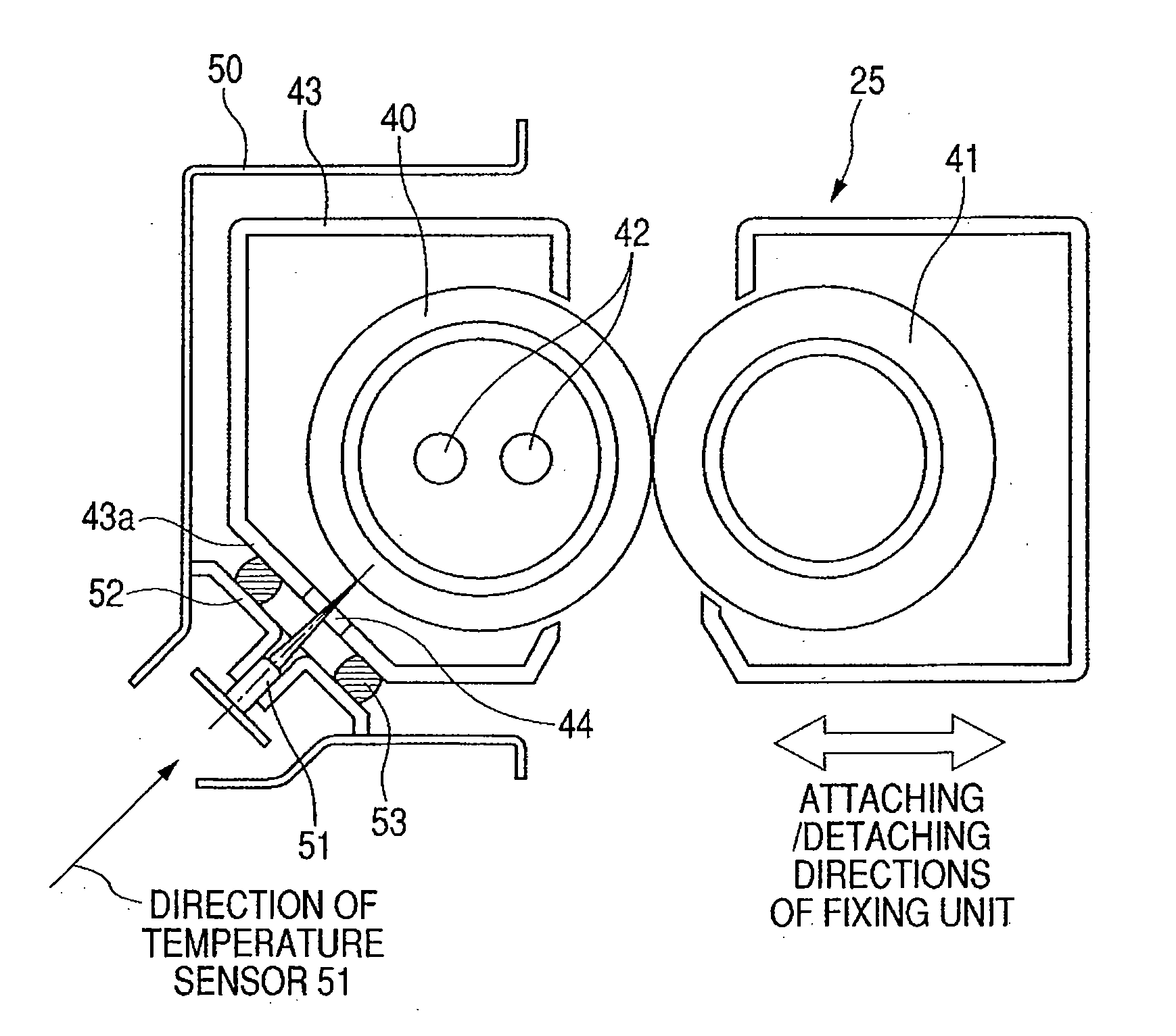
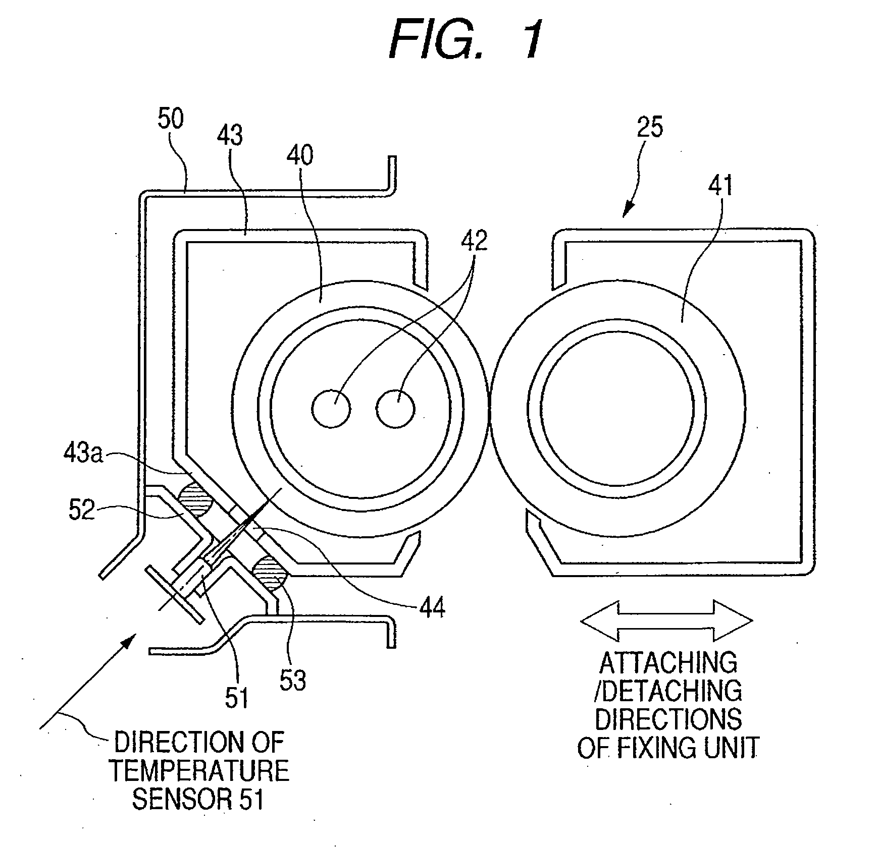
[0029]A first embodiment of the invention will be described with reference to FIGS. 1 and 4. FIG. 1 is a schematic cross sectional view of a fixing unit and its peripheral component elements in an image forming apparatus of the first embodiment of the invention. FIG. 4 is a schematic cross sectional view of the image forming apparatus (hereinafter, referred to as a printer) to which the invention is applied.

[0030]FIG. 4 illustrates a printer main body 1. An engine portion to form primary images of four colors in total of yellow, magenta, cyan, and black is arranged in an upper portion of the printer main body 1.

[0031]Print data transmitted from an external apparatus such as a personal computer is received by a controller for controlling the printer main body 1 and output as writing image data to a laser scanner 10 of each color. The laser scanner emits a laser beam onto a photosensitive drum 12 and draws a light image according to the writing image data.

[0032]The engine portion has ...

second embodiment

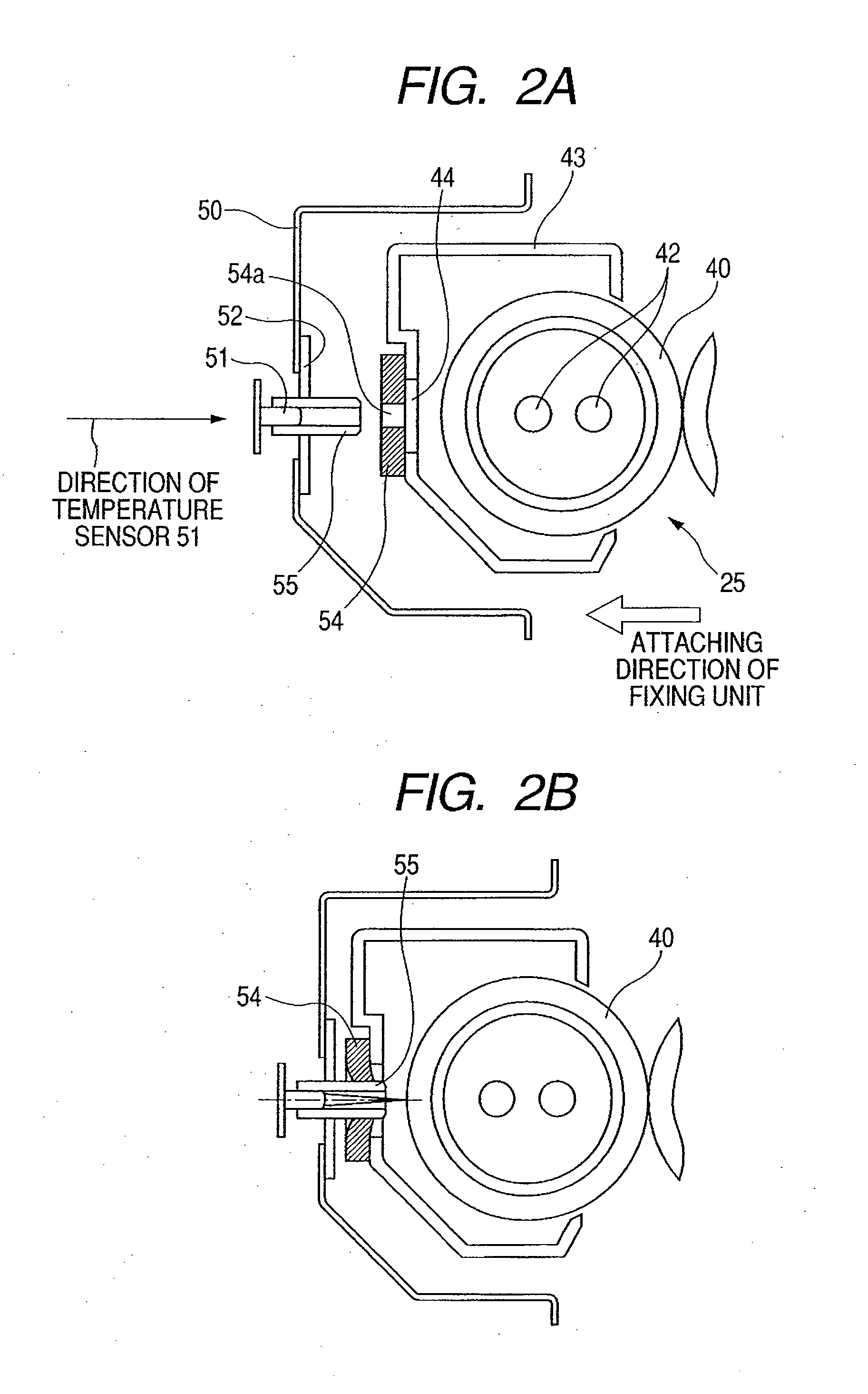
[0055]FIGS. 2A and 2B are diagrams illustrating the second embodiment. FIG. 2A illustrates a state before the fixing unit 25 is attached to the printer main body 1. FIG. 2B illustrates a state where the fixing unit 25 has been attached. In FIGS. 2A and 2B, component elements similar to those in FIG. 1 are designated by the same reference numerals and their description is omitted.

[0056]In the embodiment illustrated in FIGS. 2A and 2B, a sealing member 54 as a sealing unit is provided on the cover member 43 of the fixing unit 25. The virtual line (that is, the direction of the temperature sensor 51) connecting the temperature sensor 51 and the center of the opening portion 44 of the fixing unit in the state where the fixing unit 25 has been attached to the apparatus main body 1 is almost parallel with the direction in which the fixing unit 25 is attached to the apparatus main body 1.

[0057]In the sealing member 54, a hole portion 54a smaller than the opening portion 44 is formed near t...

third embodiment

[0060]Although the example in which the raw material itself of the sealing member can be compressed and deformed (elastic deformation) has been described in the first and second embodiments, an effect similar to that in the first embodiment can be also obtained by another construction. A third embodiment of the invention will now be described with reference to FIGS. 3A and 3B.

[0061]FIGS. 3A and 3B are schematic cross sectional views of the fixing unit 25 and its peripheral component elements according to the third embodiment of the invention. FIG. 3A illustrates a state before the fixing unit 25 is attached to the printer main body 1. FIG. 3B illustrates a state where the fixing unit 25 has been attached. A construction of the fixing unit 25 and a construction in which the contactless temperature sensor 51 has been fixed to the frame 50 of the printer main body 1 through the sensor holder 52 are similar to those in the first embodiment. Component elements similar to those in the fir...


PUM


Abstract

A sealing member which is compressed by a contactless temperature sensor and a cover member of a fixing unit is provided between the sensor and the cover member. An opening portion for temperature detection is shut off from a space around the fixing unit by the sealing member, thereby preventing the air from flowing from the opening portion into the fixing unit.

Description

BACKGROUND OF THE INVENTION[0001]1. Field of the Invention[0002]The present invention relates to an image forming apparatus such as copying apparatus and printer having a function of forming an image onto a recording medium such as a sheet and, more particularly, to an image forming apparatus having a contactless type temperature sensor.[0003]2. Description of the Related Art[0004]Hitherto, in an image forming apparatus, a toner image formed on a sheet is thermally fixed onto a sheet surface by using a fixing unit (fixing roller, fixing belt) having a heat source. Since a management of a fixing temperature in this instance is very important to stabilize sheet conveying performance and image quality, generally, proper heating control is made to the heat source while monitoring a temperature of a surface of the fixing unit by using a temperature detecting sensor.[0005]Hitherto, a contact type sensor such as a thermistor has widely been used as a temperature detecting sensor.[0006]Howe...

Claims


Application Information

Patent Timeline
Patent Type & Authority Applications(United States)
IPC IPC(8): G03G15/20
CPCG03G2215/20G03G21/20
Inventor YANO, TAKASHI
Owner CANON KK
Learn More