
Sliding mechanism, electronic apparatus and portable device

a technology of electronic equipment and sliding mechanism, which is applied in the direction of casings/cabinets/drawers, instruments, casings/cabinets/drawers, etc., can solve the problems of affecting the use effect, affecting the smoothness of the sliding mechanism, so as to reduce the size and/or flatten the apparatus

Active Publication Date: 2009-01-29
FUJITSU CONNECTED TECH LTD
View PDF6 Cites 48 Cited by
  • Summary
  • Abstract
  • Description
  • Claims
  • Application Information

AI Technical Summary

Benefits of technology

[0015]Another object of the present invention relates to a sliding mechanism used for an apparatus such as a portable device, and is to suppress shaking between housing units in an opened state, closed state or on the way to opening / closing.
[0035](5) In a portable device and an electronic apparatus where such sliding mechanism is mounted, safety and reliability can be improved along with downsizing and flatting thereof.

Problems solved by technology

However, it has been difficult to suppress wear by use and shaking by aging.
If the slider guide is exposed to the rear surface of the device, there is risk that a user touches the exposed part of the slider guide.
There is risk that a foreign object such as trash enters the clearance and the slider languishes.
If there is shaking in a single slide module, great shaking occurs to the device that is opened and closed by the slide module in opening and closing.
There is no disclosure and suggestion in Japanese Patent Application laid-Open Publication Nos. 2006-270804 and 2006-246353 concerning such requests and problems, and the structure disclosed in Japanese Patent Application laid-Open Publication Nos. 2006-270804 and 2006-246353 cannot solve the above problems.

Method used


Image

  • Sliding mechanism, electronic apparatus and portable device
  • Sliding mechanism, electronic apparatus and portable device
  • Sliding mechanism, electronic apparatus and portable device

Examples


embodiment

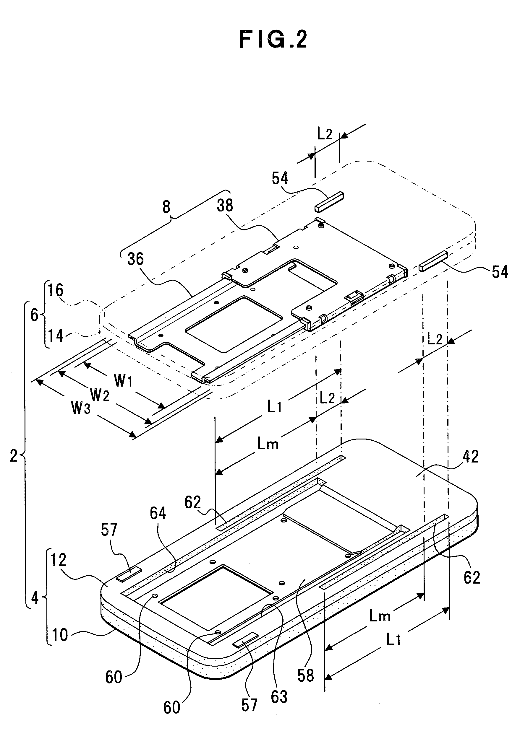
[0049]An embodiment of a sliding mechanism, an electronic apparatus and a portable device of the present invention will now be described with reference to FIG. 1. FIG. 1 is an exploded perspective view exemplifying a portable device where a sliding mechanism is mounted.

[0050]This portable device 2 is an example of a sliding mechanism, an electronic apparatus and a portable device. In this embodiment, an upper housing unit 4 as a first housing unit (for example, a movable housing unit) and a lower housing unit 6 as a second housing unit (for example, a fixed housing unit) are provided. A slide module 8 is provided between opposed surfaces of the upper housing unit 4 and lower housing unit 6. That is, the upper housing unit 4 and the lower housing unit 6 are slidably connected by the slide module 8. The upper housing unit 4, the lower housing unit 6 and the slide module 8 constitute a sliding mechanism as an example. The upper housing unit 4 and the lower housing unit 6 are compacts m...


PUM


Abstract

A sliding mechanism used for an apparatus such as a portable device suppresses shaking between housing units in an opened state, closed state or on the way to opening / closing. A slide module is provided for opposed surfaces against a first housing unit (upper housing unit) and second housing unit (lower housing unit) to be slid. The slide module slidably supports the first and second housing units. Since the slide module has a slider and a fixing part that slidably supports the slider, it is structured that in case the first and second housing units are in an opened state, the slider is not exposed through the first and second housing units. Structure is included that compared with the first and second housing units in a closed state, in case in the opened state, a guide of the slider for the fixing part of the slide module is made wider.

Description

CROSS-REFERENCE TO RELATED APPLICATIONS[0001]This application is based upon and claims the benefit of priority from the prior Japanese Patent Application No. 2007-196403, filed on Jul. 27, 2007, the entire contents of which are incorporated herein by reference.BACKGROUND OF THE INVENTION[0002]1. Field of the Invention[0003]The present invention relates generally to a sliding mechanism used for sliding a housing of a portable device such as a portable terminal device and other electronic apparatuses, and more particularly, to a sliding mechanism that slidably connects a plurality of housing units, and an electronic apparatus and portable device that have the sliding mechanism.[0004]2. Description of the Related Art[0005]A portable device such as a portable terminal device that includes a sliding mechanism is known. A housing thereof is divided into a housing unit of a display side and a housing unit of an operation side, thus each housing unit is made slidable. When such portable dev...

Claims


Application Information

Patent Timeline
IPC IPC(8): H05K7/00G06F1/16H04M1/02
CPCH04M1/0237H04B1/38
Inventor WAKIHARA, JUNJI
Owner FUJITSU CONNECTED TECH LTD
Learn More