
Zoom lens system and image pickup apparatus equipped with the same

a technology of zoom lens and image pickup, which is applied in the direction of optics, instruments, optics, etc., can solve the problems of insufficient reduction of the length of the lens system, the lens element thickness will be greater, and the zoom lens system with such a configuration can not achieve the effect of high optical performan

Inactive Publication Date: 2009-01-22
CANON KK
View PDF6 Cites 6 Cited by
  • Summary
  • Abstract
  • Description
  • Claims
  • Application Information

AI Technical Summary

Benefits of technology

[0023]According to the present invention, a compact zoom lens system with high optical performance over the entire zoom range can be provided.

Problems solved by technology

However, a zoom lens system with such a configuration can be problematic in that the lens elements will have greater lens thicknesses in accordance with the increase in the refractive powers of the lens surfaces.
For this reason, the length of the lens system cannot be sufficiently reduced, and at the same time, the zoom lens system will have difficulty in correcting the aberrations.
In addition, if a camera is to be given a collapsible function where the lens units can be collapsed and stored when the camera is not in use, increasing the refractive powers of the lens units will inevitably cause mechanical errors, such as tilting of the lens elements and the lens units.
In this case, if the sensitivity of the lens elements and the lens units is high, the optical performance can deteriorate and an image blur can occur during zooming.
In the aforementioned four-unit zoom lens systems, the light quantity tends to drop drastically in the peripheral region of the screen when the zoom lens system is at the wide-angle end or at zoom positions near the wide-angle end, thus lowering the image quality in the peripheral region of the screen.
If the movement condition of the aperture stop is not proper, it becomes significantly difficult to minimize the drastic fall-off of light quantity in the peripheral region of the screen.
Especially in the aforementioned four-unit zoom lens systems, it is extremely difficult to achieve high optical performance over the entire zoom range and to obtain a high zoom ratio at the same time if the refractive powers of the second lens unit and the third lens unit and the moving distances of the aperture stop and the third lens unit for zooming are not set properly.

Method used


Image

  • Zoom lens system and image pickup apparatus equipped with the same
  • Zoom lens system and image pickup apparatus equipped with the same
  • Zoom lens system and image pickup apparatus equipped with the same

Examples


Embodiment Construction

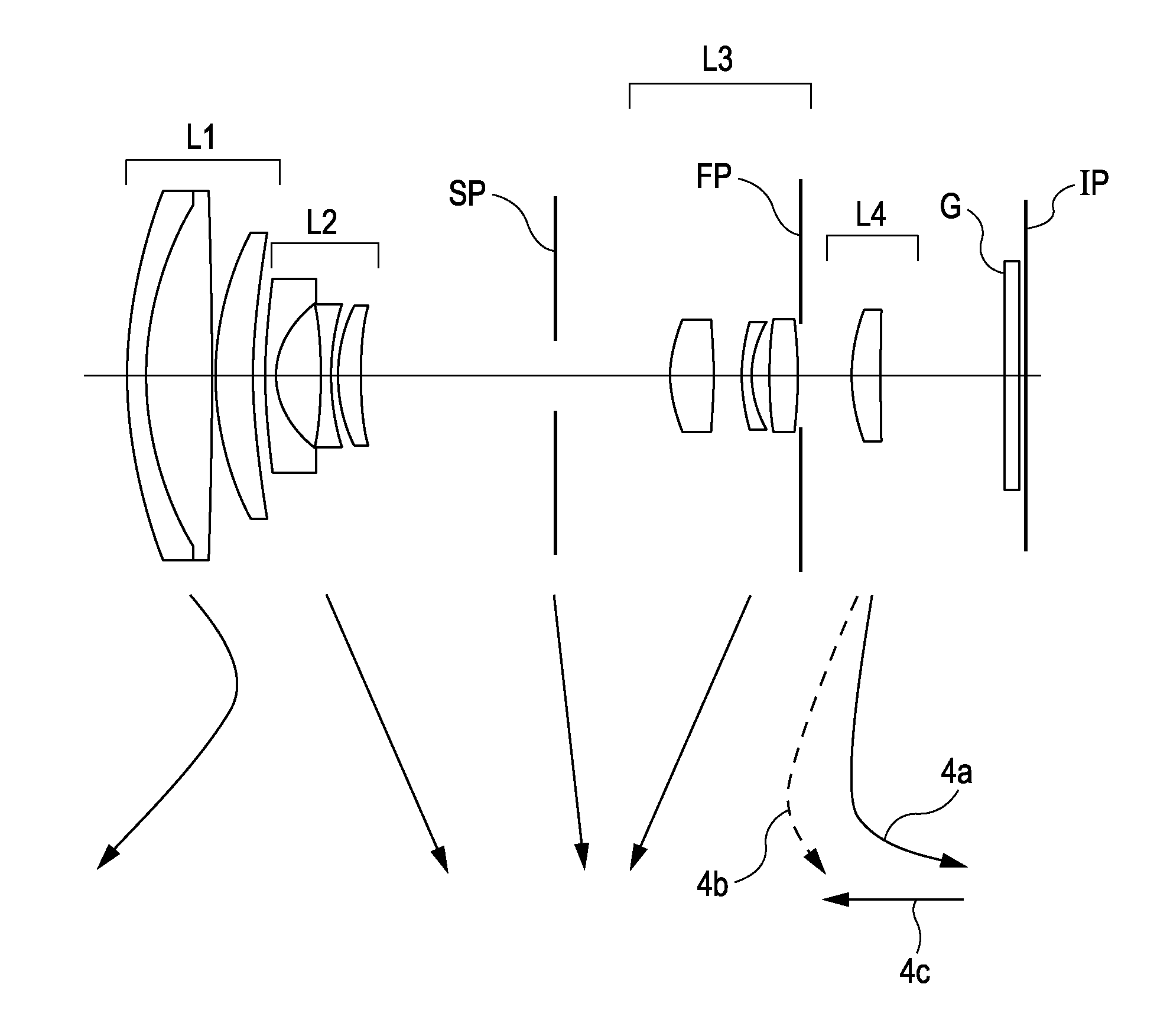
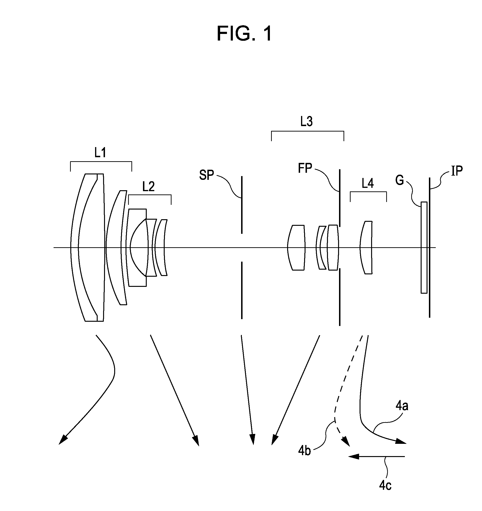
[0034]Exemplary embodiments of a zoom lens system and an image pickup apparatus equipped with the zoom lens system according to the present invention will be described below.

[0035]A zoom lens system according to an exemplary embodiment of the present invention includes a first lens unit having positive refractive power, a second lens unit having negative refractive power, an aperture stop, a third lens unit having positive refractive power, and a fourth lens unit having positive refractive power, which are arranged in that order from an object side towards an image side. The zoom lens system performs zooming by moving the lens units.

[0036]When performing zooming from a wide-angle end to a telephoto end, the first lens unit moves along a locus convex towards the image side. The aperture stop moves independently of the neighboring lens units.

[0037]FIG. 1 is a cross-sectional view of a zoom lens system according to a first embodiment of the present invention at a wide-angle end (short ...


PUM


Abstract

A zoom lens system that performs zooming by moving lens units includes, in the following order from an object side towards image side, a first lens unit having positive refractive power and movable along a locus convex towards the image side during zooming from a wide-angle end to telephoto end, a second lens unit having negative refractive power, an aperture stop movable independently of the lens units, and third and fourth lens units having positive refractive powers. The following conditions are satisfied:−0.6<f2 / f3<−0.4−0.5<MS / M3<0.9where MS and M3 respectively indicate moving distances of the aperture stop and third lens unit along an optical axis, and f2 and f3 respectively indicate focal lengths of the second and third lens units, each moving distance being a positive sign if directed towards the image side or a negative sign if directed towards the object side.

Description

BACKGROUND OF THE INVENTION[0001]1. Field of the Invention[0002]The present invention relates to zoom lens systems and image pickup apparatuses equipped with such zoom lens systems. In particular, the present invention relates to a zoom lens system that is applicable to, for example, a video camera, an electronic still camera, or a silver-halide photographic camera.[0003]2. Description of the Related Art[0004]In recent years, image pickup apparatuses containing solid-state image pickup elements and used as video cameras, digital still cameras, broadcasting cameras, film cameras that use silver-halide films, etc., have become smaller and been given increased functionality. Accordingly, there are demands for compact, high-definition zoom lens systems with reduced overall length to be used as image-taking optical systems in such image pickup apparatuses.[0005]As a zoom lens system that meets such demands, a so-called rear-focus zoom lens system is known, which performs focusing by movi...

Claims


Application Information

Patent Timeline
Patent Type & Authority Applications(United States)
IPC IPC(8): G02B15/14
CPCG02B15/173G02B15/144113
Inventor FUJISAKI, TOYOKATSU
Owner CANON KK
Learn More