
Parallel computer system

a computer system and parallel technology, applied in the field of parallel computer systems, can solve the problems of difficult realization and inability to exchange data between adjacent nodes at high speed, and achieve the effects of high performance, low cost and high speed

Inactive Publication Date: 2009-01-15
HITACHI LTD
View PDF15 Cites 43 Cited by
  • Summary
  • Abstract
  • Description
  • Claims
  • Application Information

AI Technical Summary

Benefits of technology

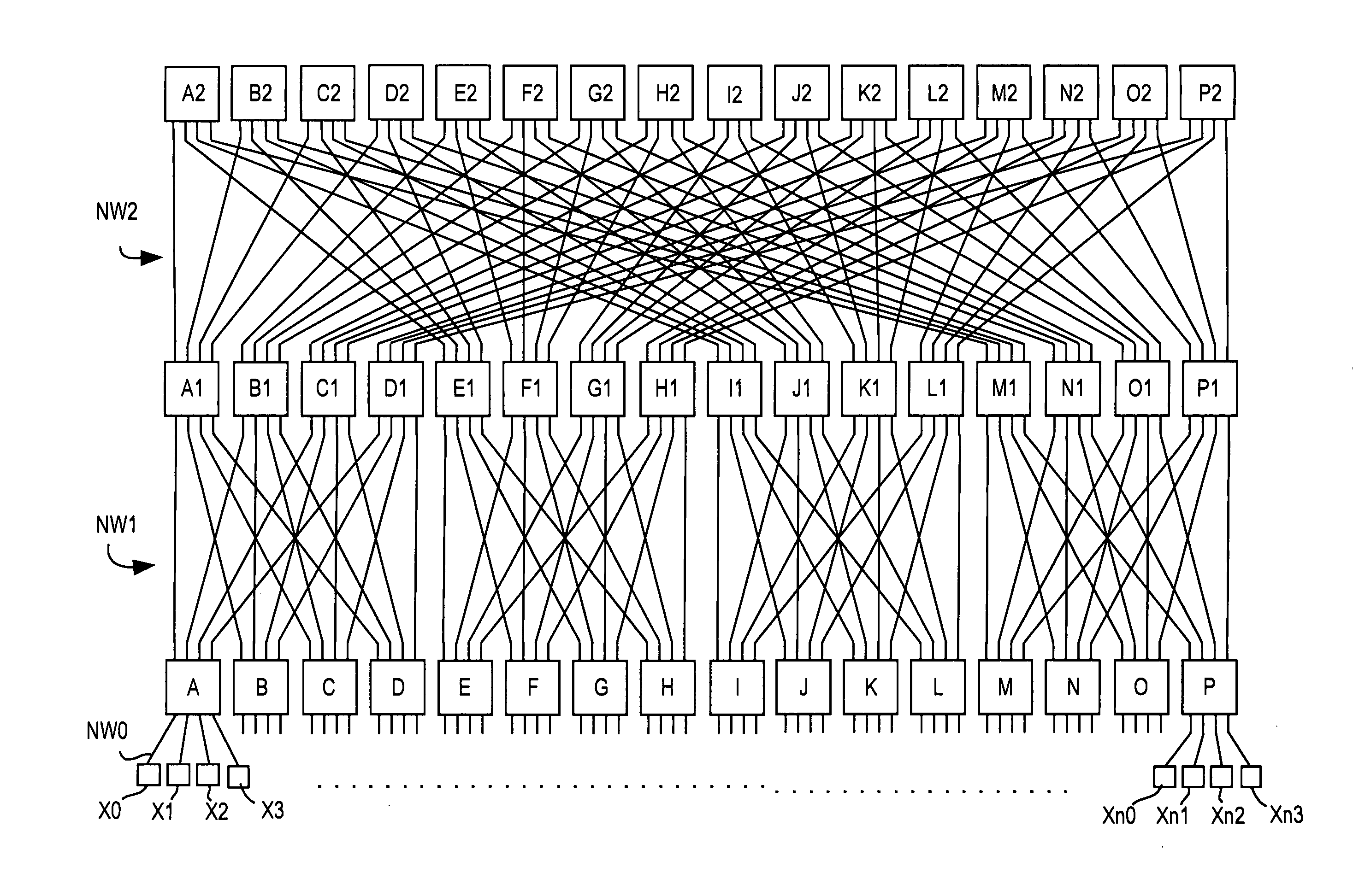
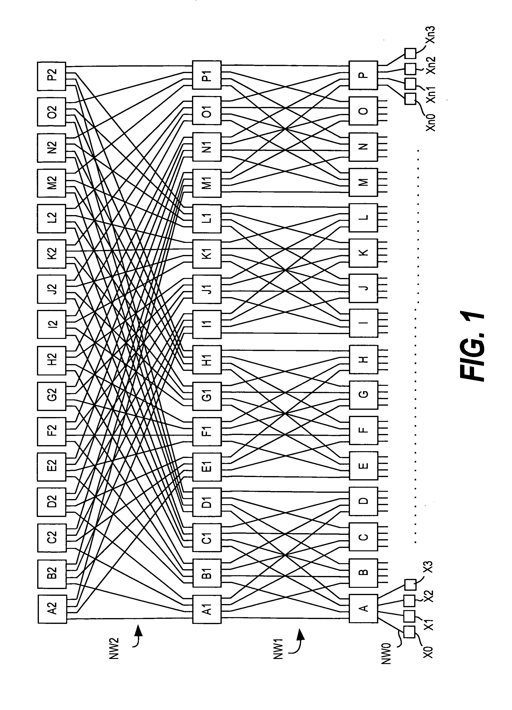
[0006]Generally employed in the parallel computer such as a supercomputer including a large number of (for example, several thousand) nodes is a technique of dividing the area of the parallel computer into a plurality of computer areas to improve the utilization efficiency and executing an application of each of different users in each computer area. Therefore, in the parallel computer such as a supercomputer, it is desirable that a computer area can be easily divided as in a fat tree, and that data be exchanged between adjacent nodes at high speed as in a torus.
[0013]According to this invention, data can be exchanged between adjacent nodes at high speed while an existing first network including a fat tree and a multistage crossbar switch, is used with only a second network added thereto. Particularly in a case of performing a computation in a multidimensional rectangular area, it is possible to exchange data between adjacent nodes at higher speed than in the case of using the existing fat tree and multistage crossbar switch. Accordingly, by using the existing first network, it is possible to build a parallel computer system with high performance at low cost.

Problems solved by technology

However, the above-mentioned case using a fat tree has a problem in that the parallel computer including a large number of nodes as described above, which aims at exchanging data between adjacent nodes at high speed on all of the nodes as in a torus connection, is difficult to realize because a huge multistage crossbar switch is necessary, requiring enormous spending on equipment.
The case of JP 2004-538548 A, in which nodes are connected by two independent networks of a global tree and a 3-dimensional torus, has a problem in that data cannot be exchanged between adjacent nodes at high speed by using the global tree, which is used for a one-to-one or one-to-many aggregate communication.

Method used


Image

  • Parallel computer system
  • Parallel computer system
  • Parallel computer system

Examples


first embodiment

[0072]FIG. 10 is a block diagram of a parallel computer system according to a first embodiment of this invention, in which the leaf switch A and the 4 nodes X0 to X3 of the fat tree shown in FIG. 1 are partially changed.

[0073]The nodes X0 to X3 are connected with each other by the network NW0 that allows the two-way communications similarly to those of FIG. 1. Adjacent 2 nodes form a pair, and there is provided a partial network NW3 for directly connecting only the nodes forming each pair. It should be noted that each node belongs to only one pair, and does not belong to another pair simultaneously.

[0074]In the example of FIG. 10, the nodes X0 and X1 form a pair, and the nodes X2 and X3 form another pair. The nodes X0 and X1 forming the pair are directly connected with each other by the partial network NW3, while the nodes X2 and X3 forming the pair are directly connected with each other by the partial network NW3. In this case, the nodes X1 and X2 are the adjacent nodes, but one no...

second embodiment

[0083]Hereinafter, a second embodiment of this invention will be described by applying the first embodiment of this invention to data transfers between adjacent nodes within a 3-dimensional rectangular area. The second embodiment of this invention will be described below after examples of the fat tree and the 3-dimensional torus to be used for comparison with the second embodiment.

[0084](3-Dimensional Rectangular Area)

[0085]FIG. 14 shows a 3-dimensional rectangular area composed of 4 nodes in each axis similarly to the 3-dimensional torus shown in FIG. 5, and indicates a process ID of each of the nodes on each of which a predetermined application is executed. FIG. 14 shows an example where the process ID of the application increases in order from the X-axis to the Y-axis to the Z-axis of the 3-dimensional rectangular area, and in the example of FIG. 14, 0 to 63 are mapped to the process IDs. In data exchanges between adjacent nodes within the 3-dimensional rectangular area, a progra...

third embodiment

[0133]FIG. 30 shows a third embodiment, which is the same as the second embodiment except that the partial network NW3 of the second embodiment is replaced by a star topology switch.

[0134]The connection between each node and the leaf switch of the fat tree is the same as that of FIG. 18. Also in this case, similarly to the second embodiment, the data exchanges within the 3-dimensional rectangular area can be executed at higher speed than the conventional fat tree.

[0135]In this case, the adjacent communications in the X-axis direction, the adjacent communications in the Y-axis direction, and the adjacent communications in the Z-axis direction cannot be performed simultaneously within a node group. For example, the X-axis direction communications between the nodes having the node IDs “000” and “100” and the Y-axis direction communications between the nodes having the node IDs “000” and “010” cannot be performed simultaneously because a conflict occurs in the path between the node havi...


PUM


Abstract

To exchange data between adjacent nodes at high speed while using an existing network including a fat tree and a multistage crossbar switch. This invention provides a parallel computer system including: a plurality of nodes each of which includes a processor and a communication unit; a switch for connecting the plurality of nodes with each other; a first network for connecting each of the plurality of nodes and the switch; and a second network for partially connecting the plurality of nodes with each other. Further, the first network is comprised of one of a fat tree and a multistage crossbar network. Further, the second network partially connects predetermined nodes among the plurality of nodes directly with each other.

Description

CLAIM OF PRIORITY[0001]The present application claims priority from Japanese application P2007-184367 filed on Jul. 13, 2007, the content of which is hereby incorporated by reference into this application.BACKGROUND OF THE INVENTION[0002]This invention relates to a parallel computer system including a plurality of processors, in particular, a system and an architecture of a supercomputer.[0003]In a parallel computer provided with a plurality of nodes including a processor, the nodes are connected with each other by a tree topology network such as a fat tree, by a multistage crossbar switch, and by other such means, and a computation processing is executed while communications such as data transfers between the nodes are performed. Particularly in a parallel computer such as a supercomputer including a large number of (for example, 1,000 or more) nodes, the fat tree and the multistage crossbar switch are used, the area of the parallel computer is divided into a plurality of computer ...

Claims


Application Information

Patent Timeline
IPC IPC(8): H04L12/50
CPCH04L49/1515G06F15/173
Inventor AOKI, HIDETAKANAGASAKA, YOSHIKO
Owner HITACHI LTD
Learn More