
Condom Ring with Multiple Vibration Modes

a technology of vibration mode and condom ring, which is applied in the field of condom ring with multiple vibration mode, can solve problems such as not being particularly good, and achieve the effects of preventing social diseases and aids from spreading, facilitating sexual fun, and significantly increasing the use of condoms

Inactive Publication Date: 2009-01-08
VICON HEALTHCARE INT
View PDF4 Cites 54 Cited by
  • Summary
  • Abstract
  • Description
  • Claims
  • Application Information

AI Technical Summary

Benefits of technology

[0007]The primary purpose of the present invention is to provide a vibrating condom ring to enjoy more fun in sex, significantly increase use of condom, and effectively prevent social diseases and AIDS from spreading.
[0008]To achieve the purpose, a vibrating condom ring of the present invention is comprised of a ring and a vibrating component. The vibrating component includes a motive element, a power supply element, multiple conduction elements, a switch element, and a control element. The switch element controls the operation of the control element; the control element is electrically connected to the motive element and the power supply element respectively through the conductive element; and the control element is capable of controlling the vibrating frequency and model. Accordingly, the user may control the vibrating frequency and model of the vibrating condom ring by means of the switch element to increase sex pleasure.

Problems solved by technology

Therefore, Centers for Disease Control of Department of Health, Taiwan launched propaganda programs to teach the younger people to always use a condom before making love; however, the results are not particularly good.
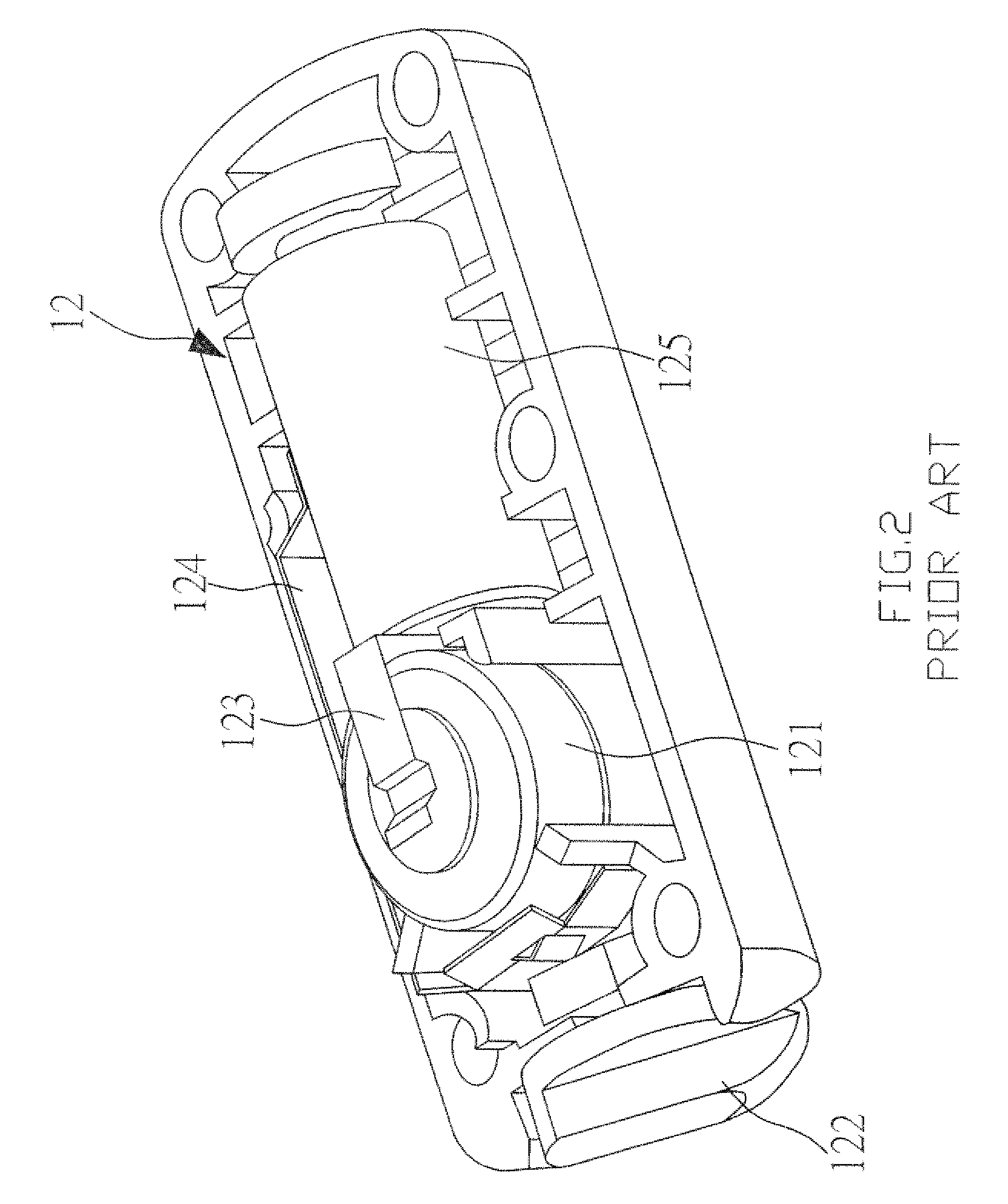
However, the vibrating condom ring of the prior art provides only one vibration at fixed frequency or one vibration mode, e.g., a single vibrating speed and that prevents readjustment depending on the individual user.

Method used


Image

  • Condom Ring with Multiple Vibration Modes
  • Condom Ring with Multiple Vibration Modes
  • Condom Ring with Multiple Vibration Modes

Examples


Embodiment Construction

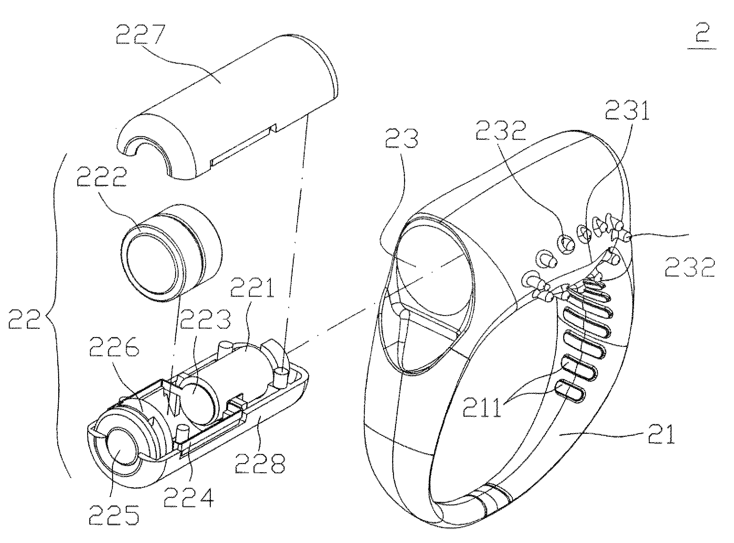
[0017]Referring to FIGS. 4 through 7, a vibrating condom ring 2 of the present invention is comprised of an insertion ring 21 and a vibrating component 22. The vibrating component 22 is disposed with a motive element 221 (e.g., a vibrating motor), a power supply element 222 (e.g., a battery) and a conductive member. The conductive member is comprised of a first conductive element 223, a second conductive element 224, and a third conductive element 229 (e.g., conductive plate or spring). The power supply element 222 is electrically connected to motive element 221 by means of the first conductive element 223, the second conductive element 224 respectively to operate the motive element 221 and the condom ring 2 to vibrate.

[0018]A switch element 225 and a control element 226 are disposed to the vibrating component 22. The switch element 225 controls operation of the control element 226 and is related to an electronic key switch. The first conductive element 223 constitutes electric conn...


PUM


Abstract

A vibrating condom ring includes a motive element, a power supply element, multiple conduction elements, a switch element, and a control element. The switch element controls the operation of the control element; the control element is electrically connected to the motive element and the power supply element respectively through the conductive element; and the control element is capable of controlling the vibrating frequency and model for the user may control the vibrating frequency and model of the vibrating condom ring by means of the switch element to increase sex pleasure.

Description

BACKGROUND OF THE INVENTION[0001](a) Field of the Invention[0002]The present invention is related to a condom ring with multiple vibration modes, and more particularly, to a power ring to be inserted onto a condom for increasing sexual funs while encouraging the use of the condom to effectively prevent spreading of social disease and AIDS.[0003](b) Description of the Prior Art[0004]Statistics shows that most of AIDS patients are in the age groups of the young and the prime of life in the world, wherein one fifth are falling in the age group of 15˜20. In Taiwan, the number of those who affected by AIDS by end of September 2006 rises up to 3422; among them, approximately 90% had infection through sex, and approximately 40% fall within the age group of 20˜29, indicating that the attitude about sex of most of the young people knowing only to indulging in pursuit of short while of sexual pleasure and satisfaction fail to develop correct and mature recognition at a time when the sex becom...

Claims


Application Information

Patent Timeline
Patent Type & Authority Applications(United States)
IPC IPC(8): A61F5/00A61H1/00
CPCA61F2005/414A61H19/34A61H19/30A61H23/0263A61H2201/165A61H19/50A61H19/00
Inventor LIN, CHIEN-FENG
Owner VICON HEALTHCARE INT
Learn More