Method, device and arrangement for measuring the dynamic behavior of an optical system

a dynamic behavior and optical system technology, applied in the field of methods, devices and arrangements for measuring the dynamic behavior of optical systems, can solve the problems of not fully developed in all aspects and complex technological aspects of adaptive optics, and achieve the effect of easy implementation and recognition and fixation by the subj

Inactive Publication Date: 2009-01-01
CARL ZEISS MEDITEC AG
View PDF9 Cites 9 Cited by
  • Summary
  • Abstract
  • Description
  • Claims
  • Application Information

AI Technical Summary

Benefits of technology

[0012]In one embodiment of the method, the optical system to be measured is a human eye. It is an aim of the method aims to stimulate an individual eye or the eye system in the visual process in order to selectively produce an excitation and an associated influence on the eye parameters. The induced changes in the eye parameters directly change the imaging properties of the eye and are therefore accessible, for example, via a wavefront measurement triggered synchronously with the excitation. This method allows analysis and measurement of the most different effects. For example, the time dependence and speed of accommodation and of the accommodative capacity, the adaptation and adaptive capacity or adaptation speed of the eye may be examined under influences such as aberration, illumination, medication, or psychic influences. The dynamic short- and long-time behavior of contact lenses, such as slippage or the like, may be examined with respect to the changes in aberration due to wearing of contact lenses. It is possible to determine the dynamic behavior of intraocular lenses (IOL) and accommodative intraocular lenses, and the reciprocal effect of the residual ciliary body on intraocular lenses, as well as the fit and movement and, possibly, the induced accommodation thereof. Also possible are connections between the physical vision and the brain performance which may possibly help discover objective conclusions about clinical pictures such as headaches due to overstress. Thus, for example, it is possible to measure dazzling effects and other time-variant effects in connection with fatigue phenomena during motoring. Dynamic optical correction may be examined, for example, in relation to occupational groups, i.e., in terms of specific visual requirements.
[0016]A particularly simple and, moreover, automated way of evaluating the optical data is possible if the aberrometer includes a wavefront analysis device. The wavefront analysis device may be, for example, a Shack-Hartmann sensor equipped with a CCD chip for storing the relevant optical information.
[0018]It is particularly advantageous if the stimulation unit is able to trigger a visual and / or mechanical and / or electrical and / or chemical stimulus. In particular, a visual stimulus may be designed to cause the optical system to undergo accommodation or iris adjustment. Thus, different stimuli may be exerted on the eye, thus also allowing simulation of everyday situations, such as an air draft or chemical stimuli caused by smoke, or the like.
[0020]Alternatively, the stimulation unit may be integrated into the aberrometer. In this case, the beam path of the stimulation unit is directly coupled into that of the aberrometer in a common housing. This enables a very compact design.
[0023]It is advantageous if the fixation object is able to emit a light stimulus that is variable in intensity and / or focus. The eye focusing the fixation object may be stimulated directly in this manner. The change in intensity may be achieved, for example, by changing the luminosity when using light sources as the active elements, or by changing the illuminance when using passive elements such as an illuminated graphic. A change in focus is possible, for example, by moving the fixation object itself, or by changing lenses disposed in front thereof.
[0024]The fixation object is preferably an illuminated graphic. This is an object which can be easily and reliably recognized and fixated by the subject and which, moreover, is easy to implement.

Problems solved by technology

These adaptive optics are technologically complex and presently not yet fully developed in all aspects.

Method used


Image

  • Method, device and arrangement for measuring the dynamic behavior of an optical system
  • Method, device and arrangement for measuring the dynamic behavior of an optical system
  • Method, device and arrangement for measuring the dynamic behavior of an optical system

Examples


Embodiment Construction

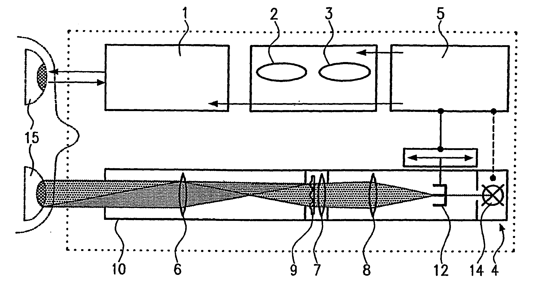
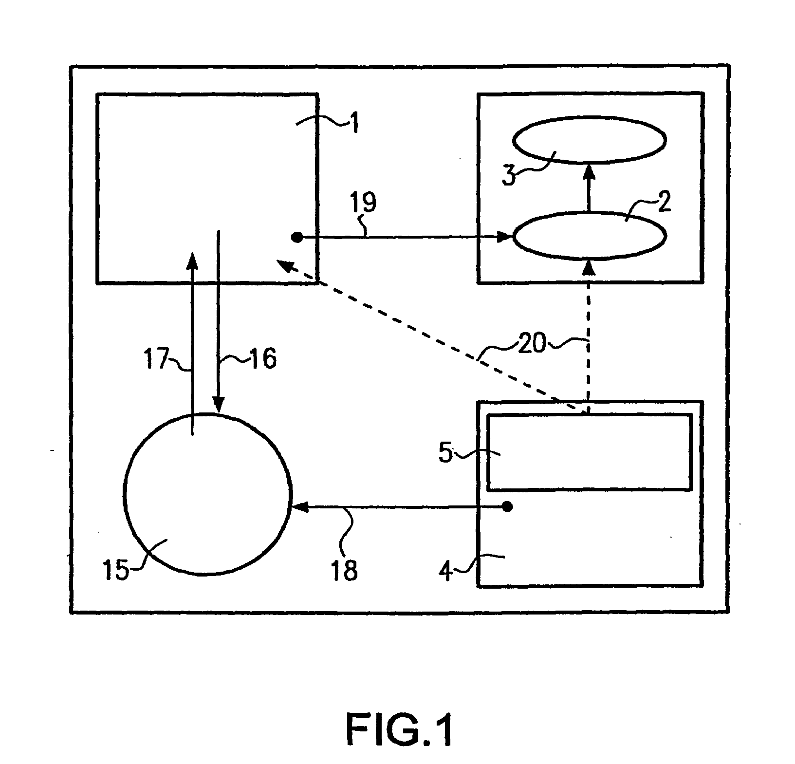
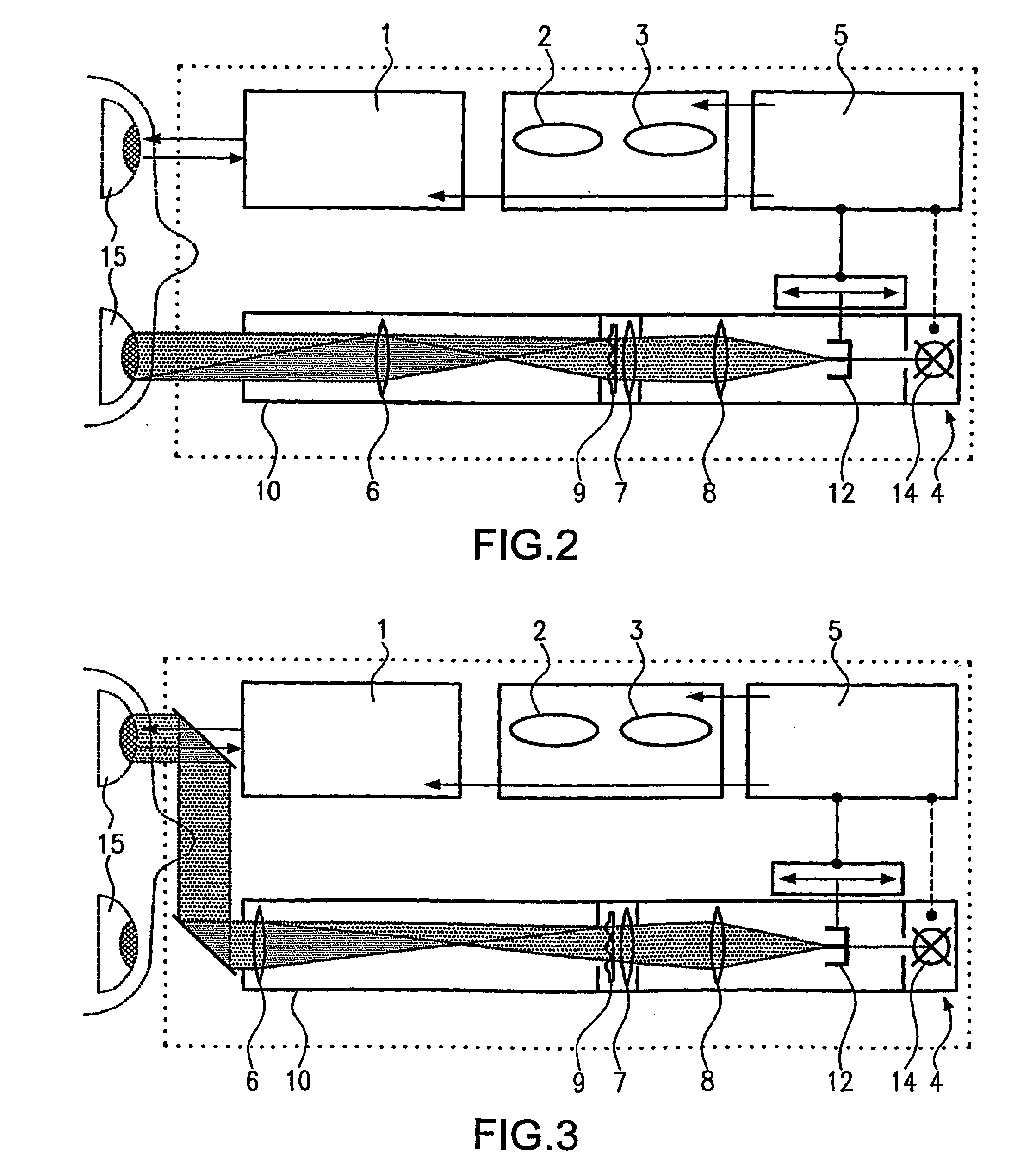
[0032]Reference is first made to FIG. 1, which is a schematic diagram of a device and the associated method sequence for dynamic stimulation and dynamic measurement of the aberrometry of an eye 15. The Figure shows the individual components and their operative connection. The device includes a unit for measuring the wavefront / aberrometry of eye 15, the unit being able to measure either both eyes at the same time or one eye at a time. In the latter case, the eye that is currently not being measured, may either look with an unrestricted view past the unit, or also look into the unit. For the sake of simplicity, the unit for measuring the wavefront / aberrometry of an eye will be referred to as “aberrometer 1” hereinafter. Aberrometer 1 emits measurement light 16 into eye 15, and the eye returns signal light 17. Measurement light 16 and signal light 17 are indicated by arrows in FIG. 1. The device further includes a device for dynamic data acquisition 2 which receives raw data 19 of aber...


PUM


Abstract

A method for measuring the dynamic behavior of an optical system is aimed at rendering the dynamic behavior of the optical system objectively detectable. To this end, the optical system to be measured is stimulated by stimuli whereby causing it to react, and the reaction is detected by means of a wave front analysis.

Description

CROSS-REFERENCE TO RELATED APPLICATIONS[0001]This application is a continuation of U.S. patent application Ser. No. 10 / 494,784, which is a U.S. National Stage Application under 35 U.S.C. §371 of PCT International Application No. PCT / EP02 / 09590, filed Aug. 28, 2002, which claims priority to German Patent Application No. DE 101 54 194.5, filed Nov. 7, 2001. Each of these applications is incorporated herein by reference as if set forth in its entirety.BACKGROUND[0002]The present invention relates to a method, device and arrangement for measuring the dynamic behavior of an optical system.[0003]Analysis of optical wavefronts of imaging and laser systems has become increasingly important because it is the starting point for improving the quality of these systems. The availability of commercial Shack-Hartmann sensors (such as SCLA series, WavefrontSciences, http: / / wavefrontsciences.com) allows aberrations to be detected very accurately and classified in the form of Zernike polynomials of d...

Claims


Application Information

Patent Timeline
Patent Type & Authority Applications(United States)
IPC IPC(8): A61B3/10A61B3/02A61B3/113A61B3/103
CPCA61B3/10A61B3/103A61B3/1015
Inventor VOGELSANG, HARTMUTBERGT, MICHAELDICK, MANFREDMAEUSEZAHL, HOLGERSCHROEDER, ECKHARD
Owner CARL ZEISS MEDITEC AG
Why Eureka
Try Eureka