Tool Head Structure

a tool head and tool head technology, applied in the direction of manufacturing tools, wood boring tools, transportation and packaging, etc., can solve the problems of screw head damage, increase the cost, and reduce the whole work efficiency, and achieve the effect of easy engagement with the screw head

Inactive Publication Date: 2009-01-01
CHEN BO SHEN
View PDF10 Cites 4 Cited by
  • Summary
  • Abstract
  • Description
  • Claims
  • Application Information

AI Technical Summary

Benefits of technology

[0014]The primary objective of the present invention is to provide a tool head structure which can easily engage with the screw and is unlikely to skid.
[0015]In order to achieve the abovementioned objective, the tool head structure comprises two cutting edges located at the center of the front end thereof. Between the two cutting edges is formed a ridge line, at the central axis of the tool head structure is formed a chisel point. By such arrangements, the tool head structure of the present invention can solve the problems of easy slipping and being unable to screw the damaged screw in.
[0016]The second objective of the present invention is to provide a tool head structure which can directly drill a hole on the working surface.
[0018]It is to be noted that, the tool head structure of the present invention comprises two cutting edges at the center of the front end thereof, a ridge line and a central chisel point, and a plurality of protruding driving portions which are shaped correspondingly to the screwing recess of the screw and formed with scraping surfaces. Moreover, the cutting direction of the scraping surface is the same as the screwing direction of the screw. By such arrangements, the tool head structure of the present invention can not only effectively drive the damaged screw to screw in and solve the problem of being unable to remove the damaged screw, but also effectively drill a hole on the working surface for an accommodation of a screw which has been screwed in.
[0019]At last, behind the two cuffing edges are formed two flank portions, and each flank portion is correspondingly linked up with the concave engaging portions. By such arrangements, the powder caused during shoveling the tool head structure into bottom of the screwing recess can be quickly discharged from the flank portion linked up with the concave engaging portion. Hence, the tool head structure of the present invention can smoothly discharge the caused powder.

Problems solved by technology

1. The screw was often screwed in an embedded manner to obtain a smooth and nice looking working surface, but the corresponding embedding working procedure of the screw head is troublesome, the operator must replace the tool head with drill bit to machine an embedding recess, and then replace the tool head again to screw the screws, thus greatly increasing the cost.
2. The head portion of the screw is often damaged by a damaged screwdriver head, and the damaged head of the screw will cause the screw unable to continue the screwing operation, so the operator must remove the damaged screw as soon as possible, thus reducing the whole work efficiency.
3. During a general screwing operation, the unbalanced force applied by the operator and the poor contact angle between the screwing tool and the screw often cause the screw head to be damaged, or a slippage during operation causes the unexpected injuries, thus not only causing the screw unable to continue the screwing operation, but also causing the severe problem of injury.
1. The end portion of the drill cone 11 is extended to form four claw portions 12, so there is not a key ridge line of a general drill, but the four angle points or four equally divided cross bevel edge. Hence, this drill cone 11 has a poor grasping ability, thus often skidding on the surface of the machining object during an electric drive operation.
2. The engagement of the claw portions 12 of the drill cone 11 with the screwing recess of the damaged screw makes the claw portions 12 grasp the inner of the screwing recess of the screw, but the four claw portion 12 with cutting edges 121 doesn't have the chisel point which is the most important during the drilling operation, so the hole drilling ability of this drill cone 11 is relatively poor.
3. The end portion of the drill cone 11 is extended to form four claw portions 12, and a special machining method is required to form the four cutting edges 121 of different directions and angles, hence the working procedure is complicated and the machining difficult is relatively high.

Method used


Image

  • Tool Head Structure
  • Tool Head Structure
  • Tool Head Structure

Examples


Embodiment Construction

[0028]The present invention will be clearer from the following description when viewed together with the accompanying drawings, which show, for purpose of illustrations only, the preferred embodiment in accordance with the present invention.

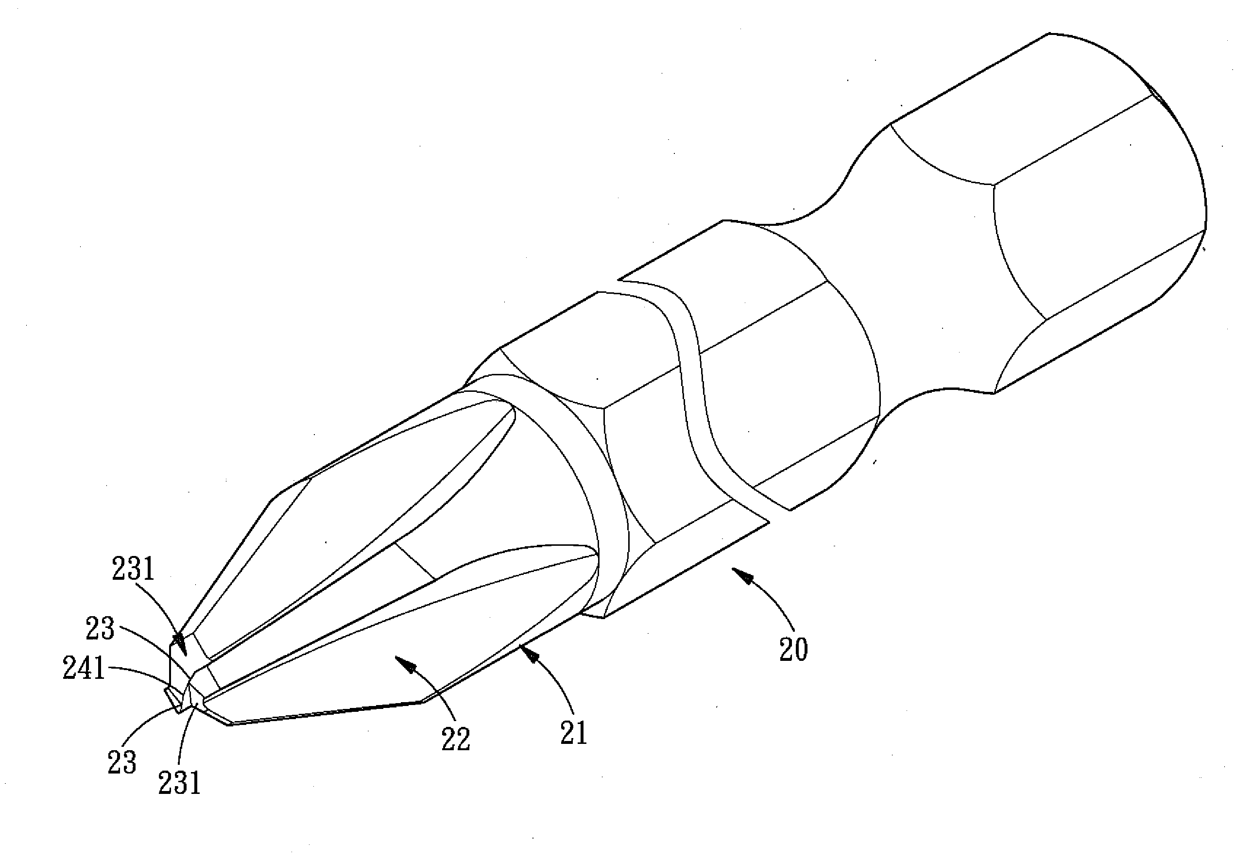
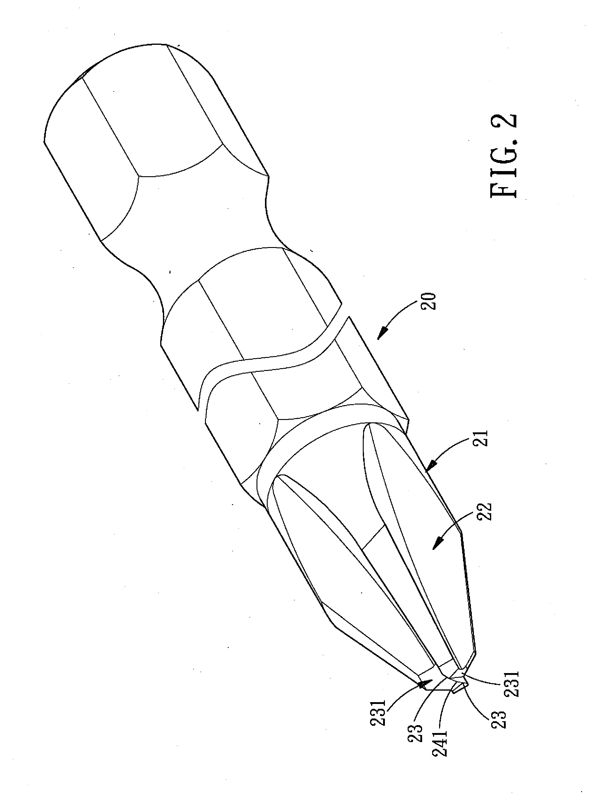
[0029]Referring to FIGS. 2-4, a tool head structure 20 in accordance with the present invention is integrally formed. One end of the tool head structure 20 is in the form of a hexagonal column for assembling with the relevant tool, and the other end of the tool head structure 20 is equally formed with four protruding driving portions 21 shaped correspondingly to the cross-shaped screwing recess 31 of the screw 30. Between each two adjacent protruding driving portions 21 is formed a concave engaging portion 22. The tool head structure 20 is characterized in that:

[0030]Two cutting edges 23 are formed at the convergence center of the protruding driving portions 21 and the engaging portions 22. The two cutting edges 23 are parallel to each other in o...


PUM


Abstract

A tool head structure is used to screw a general screw or screw a damaged screw and comprises two cutting edges located at the center of the front end thereof. Between the two cutting edges is formed a ridge line, at the central axis of the tool head structure is formed a chisel point, and behind the two cutting edges are formed two concave flank portions, and each flank portion is correspondingly linked up with the concave engaging portion. By such arrangements, the tool head structure of the present invention can solve the problem of easy slipping and being unable to remove the damaged screw.

Description

BACKGROUND OF THE INVENTION[0001]1. Field of the Invention[0002]The present invention relates to a tool head structure which is used to screw the general screw and screw the damaged screw and further can directly drill a hole on the working surface.[0003]2. Description of the Prior Art[0004]Conventionally, when using the tool heads (such as: slot screwdrivers, cross screwdrivers or star screwdrivers) to screw various screws, it often causes the following problems:[0005]1. The screw was often screwed in an embedded manner to obtain a smooth and nice looking working surface, but the corresponding embedding working procedure of the screw head is troublesome, the operator must replace the tool head with drill bit to machine an embedding recess, and then replace the tool head again to screw the screws, thus greatly increasing the cost.[0006]2. The head portion of the screw is often damaged by a damaged screwdriver head, and the damaged head of the screw will cause the screw unable to con...

Claims


Application Information

Patent Timeline
IPC IPC(8): B25B23/08
CPCB23B51/00B27G15/00B25B15/005B23B2251/66
Inventor CHEN, BO-SHEN
Owner CHEN BO SHEN
Why Eureka
Try Eureka