Cap structure for zipper

a zipper and cap structure technology, applied in the direction of snap fasteners, slide fasteners, press-button fasteners, etc., can solve the problems of difficult pulling of the pull tab, user's large force, complex etc., and achieve the effect of easy assembly of the zipper slid

Inactive Publication Date: 2009-01-01
LIN YU PAU
View PDF2 Cites 0 Cited by
  • Summary
  • Abstract
  • Description
  • Claims
  • Application Information

AI Technical Summary

Benefits of technology

[0007]It is an object of the present invention to provide a cap structure for a zipper. The cap and the resilient tap are combined previously for assembling the slide of the zipper easier. The resilient tap has an aperture, and the cap has a concave. Therefore, the resilience of the resilient tap is increased, the resilient tap has more space to allow for bending, and the force required to pull the slide of the zipper is less.
[0009]The present invention has a number of advantages, which are described below. The resilient tap is assembled inside the cap to form a cap structure. Therefore, the cap structure is assembled to the slide of the zipper to complete the assembly of the zipper slide. The assembly of the slide of the zipper is easier. Moreover, a user only needs to pull the pull tab with a small force to move the zipper slide.

Problems solved by technology

However, when a manufacturer has to assemble the resilient tap with the zipper slide, and then cover the cap on the slide of the zipper to assemble the zipper slide.
The assembly of the slide of the zipper is complex and inconvenient.
Moreover, a user must use a large force to pull the pull tab to bend the resilient tab.
The pulling of the pull tab is difficult.

Method used


Image

  • Cap structure for zipper
  • Cap structure for zipper
  • Cap structure for zipper

Examples


Embodiment Construction

[0020]The following detailed description is of the best presently contemplated modes of applying the invention. This description is not intended to be taken in a limiting sense, but is made merely for the purpose of illustrating general principles of embodiments of the invention. The scope of the invention is best defined by the appended claims.

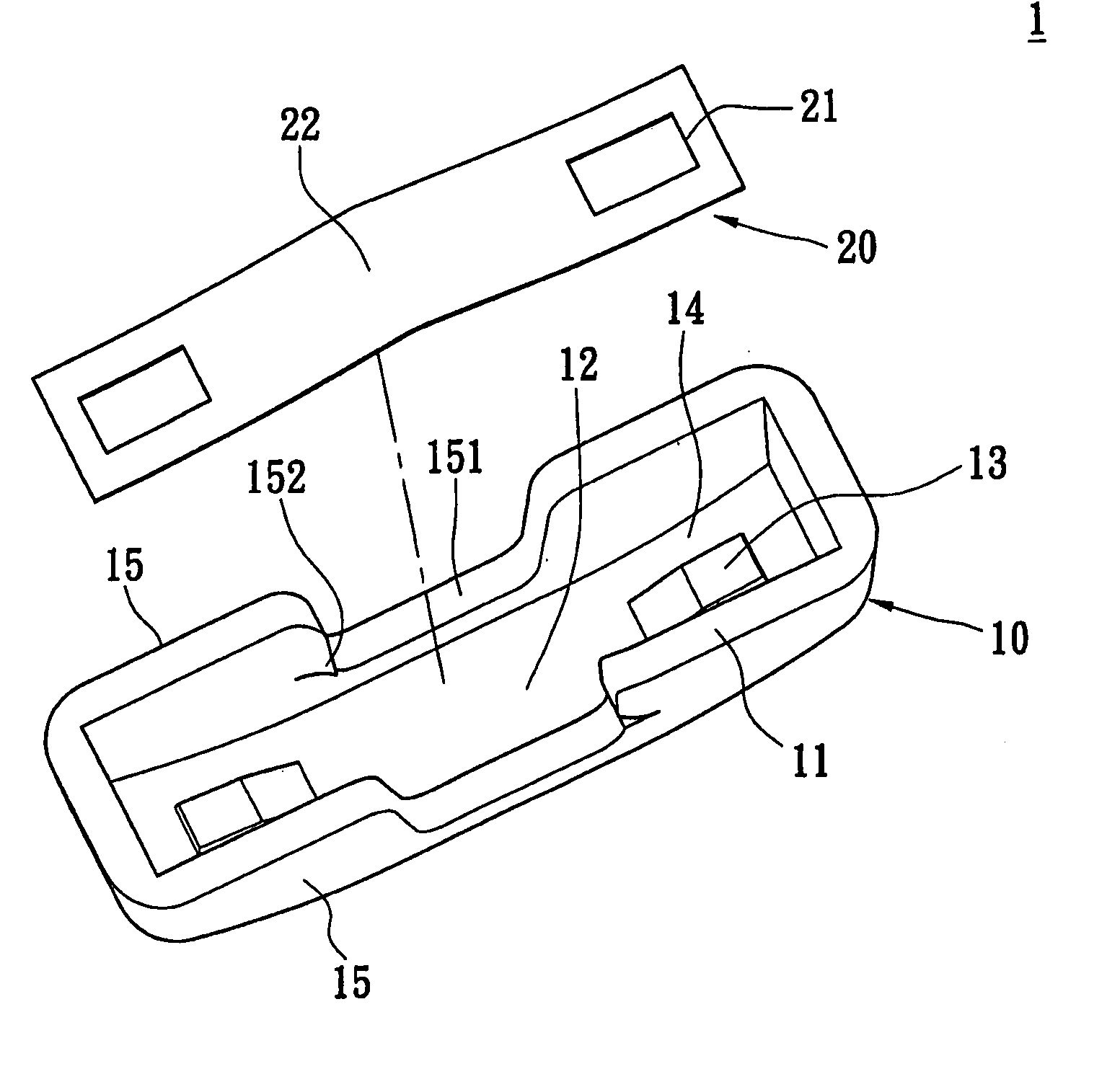
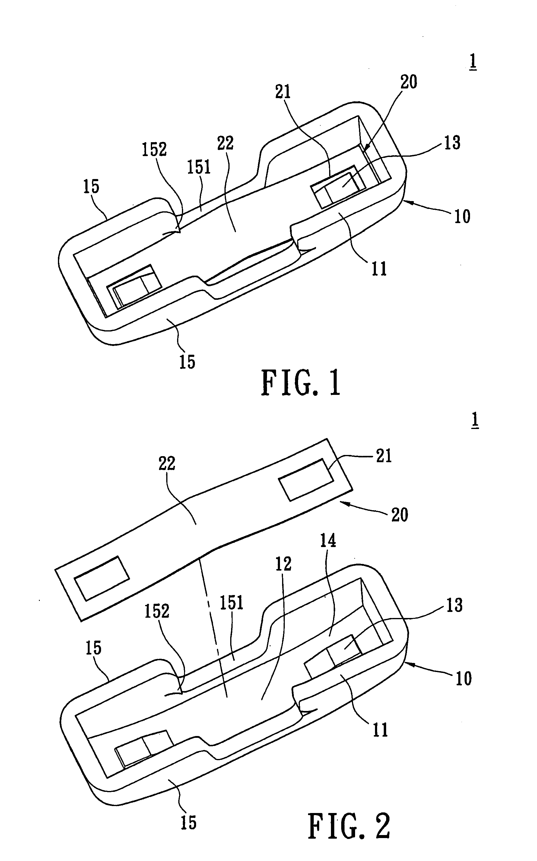
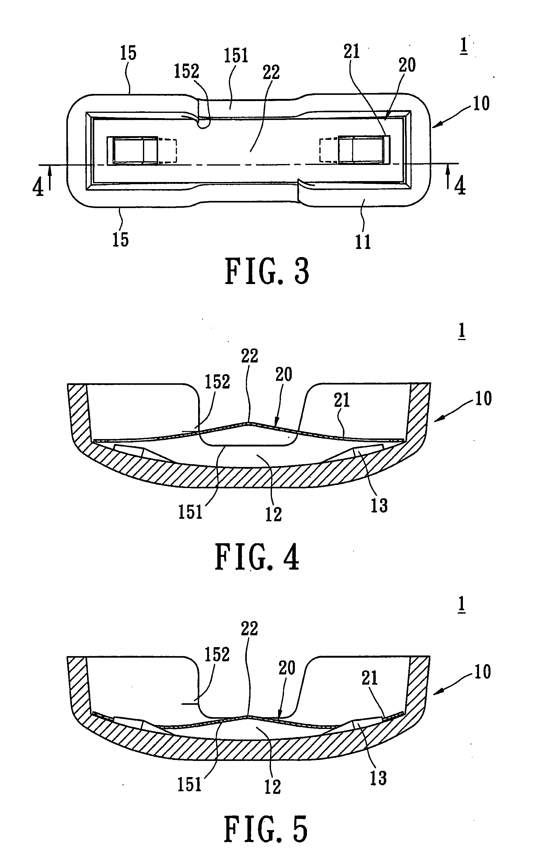
[0021]Please refer to FIGS. 1 and 4, which show a cap structure for a slide of the zipper of the present invention. The cap structure for a slide of the zipper includes a cap 10 and a resilient tap 20.

[0022]The cap 10 has a containing groove 12 formed on the bottom surface 11 thereof. Two lugs 13 are disposed on the opposite ends of the containing groove 12 respectively. The bottom surface of the containing groove 12 has a concave portion 14 between the opposite sides of each of the lugs 13 and the walls of the containing groove 12. The bottom of the concave portion 14 is lower than the top of the lugs 13.

[0023]The two lengthwise sides of the...


PUM


Abstract

A cap structure for a zipper includes a cap and a resilient tab. The cap has a containing groove formed on the bottom surface thereof. At least one lug is disposed on the bottom surface of the containing groove. The bottom of the concave portion is lower than the top of the lug. Two sides of the cap each have a side wall. Each of the side walls has a recess opening that communicates with the containing groove. The resilient tap is disposed within the containing groove and the resilient tap abuts against the limiting portions. One end of the resilient tap has an aperture that corresponds to the lug. Therefore, the resilient tap and cap are combined to form the cap structure. Because the space for the resilient tap to bend is bigger, the force for pulling the slide of the zipper is smaller.

Description

BACKGROUND OF THE INVENTION[0001]1. Field of the Invention[0002]The present invention relates to a cap structure for a zipper and in particular to a cap structure assembled on the slide of the zipper and having a resilient tap installed within the cap structure.[0003]2. Description of Related Art[0004]In general, a slide of a zipper is locked on interlocking teeth of a zipper tape (not shown in the figure). The slide of the zipper structure includes a zipper slide, a pull tab, a hook, a resilient tap, and a cap. The top of the slide of the zipper has two holding bases. A hole of the pull tab is looped around one of the holding bases of the zipper slide. The hook is disposed movably inside of the zipper slide. The resilient tap is disposed on the slide of the zipper and attached to the top of the hook. Furthermore, the cap is covered on the pull tab to lock the resilient tap inside the cap. The top of the pull to passes through a concave portion of the cap.[0005]When a user wants to ...

Claims


Application Information

Patent Timeline
Patent Type & Authority Applications(United States)
IPC IPC(8): A44B19/26
CPCA44B19/308Y10T24/2586Y10T24/2561
Inventor LIN, YU-PAU
Owner LIN YU PAU
Why Eureka
Try Eureka