Assembly with hemostatic and radiographically detectable pellets

Inactive Publication Date: 2008-11-27
SENORX
View PDF100 Cites 50 Cited by
  • Summary
  • Abstract
  • Description
  • Claims
  • Application Information

AI Technical Summary

Benefits of technology

[0013]The invention is generally directed to a remotely imagable pellet system suitable for deployment at a site within a patient's body, particularly a biopsy or lumpectomy site such as in a patient's breast from which tissue has been removed. The imagable pellet system has a plurality of hemostatic pellet members formed of material such as a polysaccharide such as starch (e.g. cornstarch) sufficient to accelerate thrombus formation at the site and one or more radiographically detectable pellets. The radiographically detectable pellets preferably have a radiopaque element to make the pellet radiographically detectable. The radiopaque element is preferably non-magnetic to facilitate or to not otherwise interfere with magnetic resonance imaging (MRI). The radiographically detectable pellet(s) are preferably at least in part formed of bioabsorbable polymeric material. The hemostatic pellets reduce bleeding at the site and in turn minimize development of hematoma.
[0018]The system preferably has a pusher pellet at the proximal most position within the delivery tube which is formed of bioabsorbable polymeric material such as polyethylene glycol and which is slightly larger than the more distal starch or polysaccharide pellets. The pusher pellet is the about the same size as the radiographically detectable bioabsorbable pellet and should have sufficient strength properties to avoid deformation when pushing the other pellets out of the delivery tube into the intracorporeal site.
[0020]Upon being discharged into the intracorporeal target site, the hemostatic pellets quickly take up water from body fluid at the site and initiate the clotting process. The at least one radiographically detectable pellet at the site enables short term detection (at least three weeks, preferably at least four weeks but less than a year) by remote USI and preferably long term detection by remote mammographic imaging or MRI identification.

Problems solved by technology

However, radiographically visible tissue features, originally observed in a mammogram, may be removed, altered or obscured by the biopsy procedure, and may heal or otherwise become altered following the biopsy.
This, in turn, can result in follow-up treatments being misdirected to an undesired portion of the patient's tissue.
Such a marker enables a follow-up procedure to be performed without the need for traditional radiographic mammography imaging which, as discussed above, can be subject to inaccuracies as a result of shifting of the location wire as well as being tedious and uncomfortable for the patient.

Method used


Image

  • Assembly with hemostatic and radiographically detectable pellets
  • Assembly with hemostatic and radiographically detectable pellets
  • Assembly with hemostatic and radiographically detectable pellets

Examples


Embodiment Construction

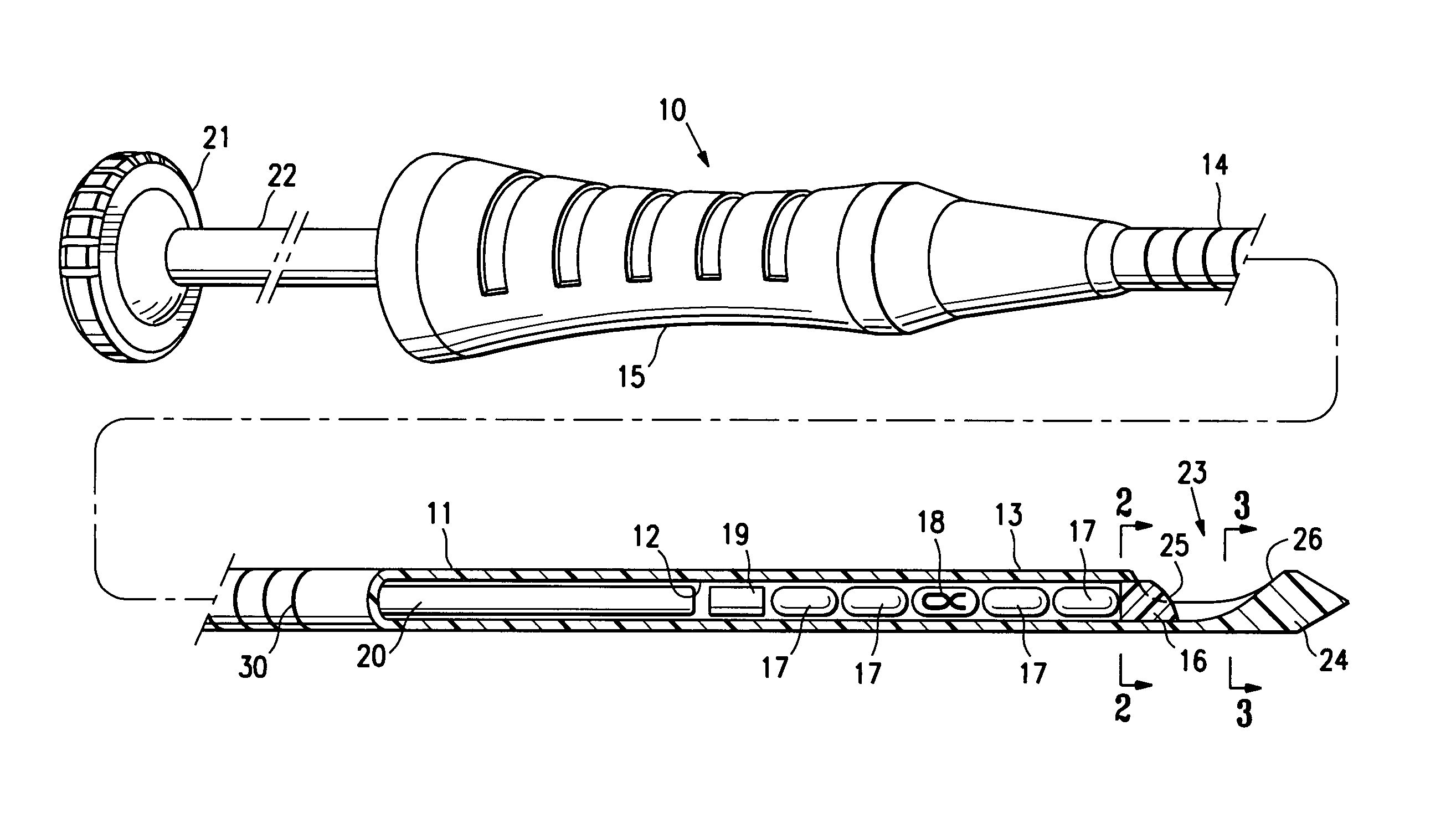
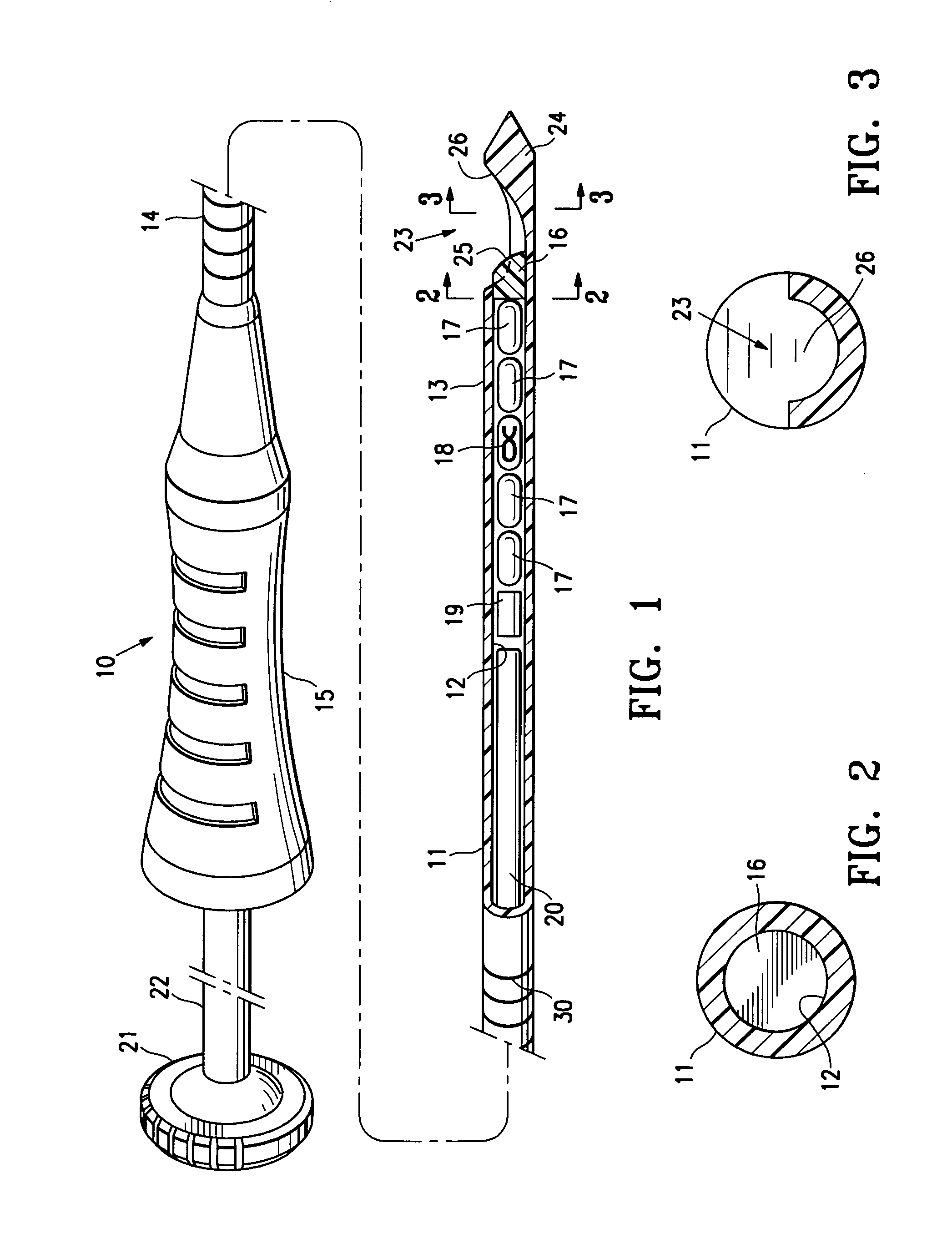
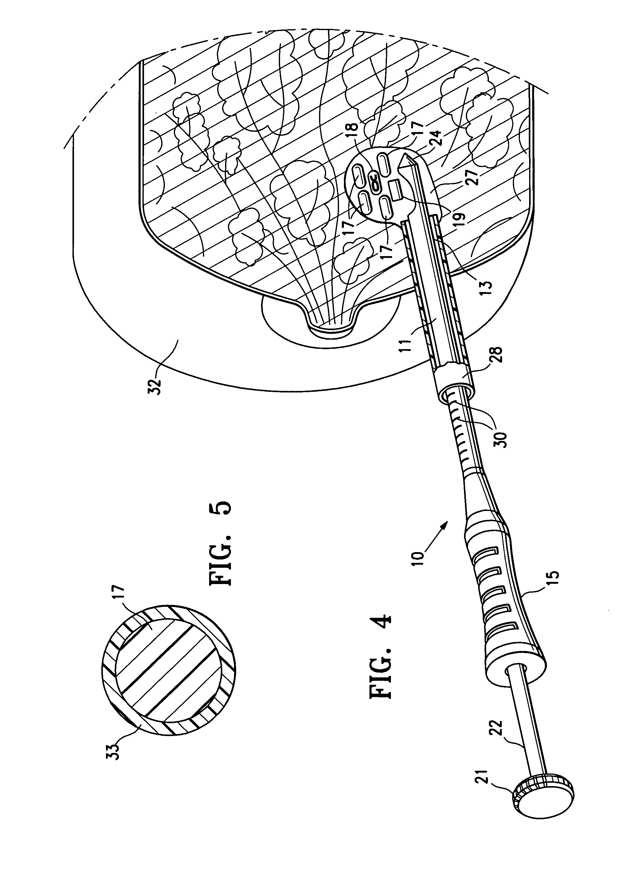
[0029]FIG. 1 illustrates marker delivery system 10 embodying features of the invention which include a delivery tube or cannula 11 with an inner lumen 12, a distal portion 13, and a proximal portion 14 with a handle 15. A releasable distal plug 16, two pairs of hemostatic pellets 17 formed of polysaccharide (e.g. starch) and a radiographically detectable marker pellet 18 between the two pairs of pellets 17 are shown disposed within the inner lumen 12. A pusher pellet 19 is located proximal to the pellets 17 and 18. A plunger 20 is slidably disposed within the inner lumen 12 and is provided with a head 21 on the proximal end 22 to allow an operator to press the plunger further into the inner lumen 12 and push the releasable plug 16, the pellets 17 and 18 and the pusher pellet 19 out of the discharge port or opening 23 in the distal end 24 of delivery cannula 11. Cannula handle 15 allows an operator to hold the cannula steady while pressing plunger 20 to discharge the pellets, e.g. in...


PUM


Abstract

The remotely imagable pellet system described has a plurality of pellets disposed within a delivery tube or cannula that are formed at least in part of a polysaccharide such as starch and at least one radiographically detectable bioabsorbable pellet which preferably has a radiopaque element. The radiographically detectable bioabsorbable pellet has at least one and preferably two pellets proximal and distal thereto which are formed of polysaccharide.

Description

RELATED APPLICATIONS[0001]This application is a continuation-in-part of application Ser. No. 11 / 881,264, filed on Jul. 26, 2007, which claims priority from provisional application Ser. No. 60 / 835,740, filed on Aug. 4, 2006, all of which are incorporated herein by reference in their entirety and from which priority is claimed.FIELD OF THE INVENTION[0002]The invention is generally directed to remotely detectable, intracorporeal marker pellets and devices and methods for the delivery of such marker pellets to a desired location within a patient's body such as a biopsy or lumpectomy site.BACKGROUND OF THE INVENTION[0003]In diagnosing and treating certain medical conditions, it is often desirable to mark a suspicious body site for the subsequent taking of a biopsy specimen, for delivery of medicine, radiation, or other treatment, for the relocation of a site from which a biopsy specimen was taken, or at which some other procedure was performed. As is known, obtaining a tissue sample by b...

Claims


Application Information

Patent Timeline
IPC IPC(8): A61B6/00
CPCA61B19/54A61B2017/00004A61B2017/00831A61B2017/00898A61B2019/5408A61B2019/5425A61B2019/5462A61B2019/5487A61M37/0069A61B90/39A61B2090/3908A61B2090/3925A61B2090/3962A61B2090/3987
Inventor JONES, MICHAEL L.LUBOCK, PAUL
Owner SENORX
Why Eureka
Try Eureka