Walk behind power tool vibration control handle

Inactive Publication Date: 2008-11-27
CHAPPLE LARRY JAKE +1
View PDF24 Cites 15 Cited by
  • Summary
  • Abstract
  • Description
  • Claims
  • Application Information

AI Technical Summary

Benefits of technology

[0004]Embodiments of the present handle provide considerable vibration dampening while retaining controllability of the power tool.
[0006]The power tool for use with this handle includes a frame member that is attached to the power tool. Attached to the frame member is a handle assembly, which the operator grasps during operation of the power tool. The unwanted vibrations transmitted to the operator during operation of the power tool are transferred, at least in part, in a wave form through the power tool's frame member to its handle and then to the operator's hands and arms. Such wave forms have node points where there is relatively little or no vibration. Methods for determining node points are well known in the industry. Node-point detection requires only ordinary research, analysis, and testing of equipment. By attaching a power tool's handle assembly at a node point on the frame member of the tool, the amount of vibration transferred from the tool to the operator's hands and arms is decreased.
[0007]In one preferred embodiment of the present invention, the handle assembly for a power tool is attached to the frame member of the power tool via an isolator chassis assembly that is located at a vibration node point of the frame member. The isolator chassis is made up of two plates, one mounted to the frame member and the other mounted to the handle assembly. Resilient material, which is preferably at least one grommet made of rubber or a rubber-like material, such as polychloroprene, or polyurethane, is located between the frame-member-mounted isolator plate and the handle-assembly-mounted isolator plate. Much of the vibration of a power tool is generated in the upper portion of the frame member, and the resilient material helps dampen any vibrations transmitted to the user. Accordingly, in this embodiment, the frame member connects to the frame-member-mounted isolator plate, which contacts resilient material, which contacts the handle-assembly-mounted isolator plate, which connects to the handle assembly. In this way, there is no metal-to-metal contact between the frame member and the handle assembly. The decreased metal-to-metal contact further helps to limit the transfer of vibrations to the operator.

Problems solved by technology

These tools impart considerable vibrations through the handle to the operator's hands and arms.
Such vibration transmissions are uncomfortable nuisances that potentially cause fatigue, stress, and injuries.

Method used


Image

  • Walk behind power tool vibration control handle
  • Walk behind power tool vibration control handle
  • Walk behind power tool vibration control handle

Examples


Embodiment Construction

[0021]While the invention is susceptible of various modifications and alternative constructions, certain illustrated embodiments thereof have been shown in the drawings and will be described below in detail. It should be understood, however, that there is no intention to limit the invention to the specific form disclosed, but, on the contrary, the invention is to cover all modifications, alternative constructions, and equivalents falling within the spirit and scope of the invention as defined in the claims.

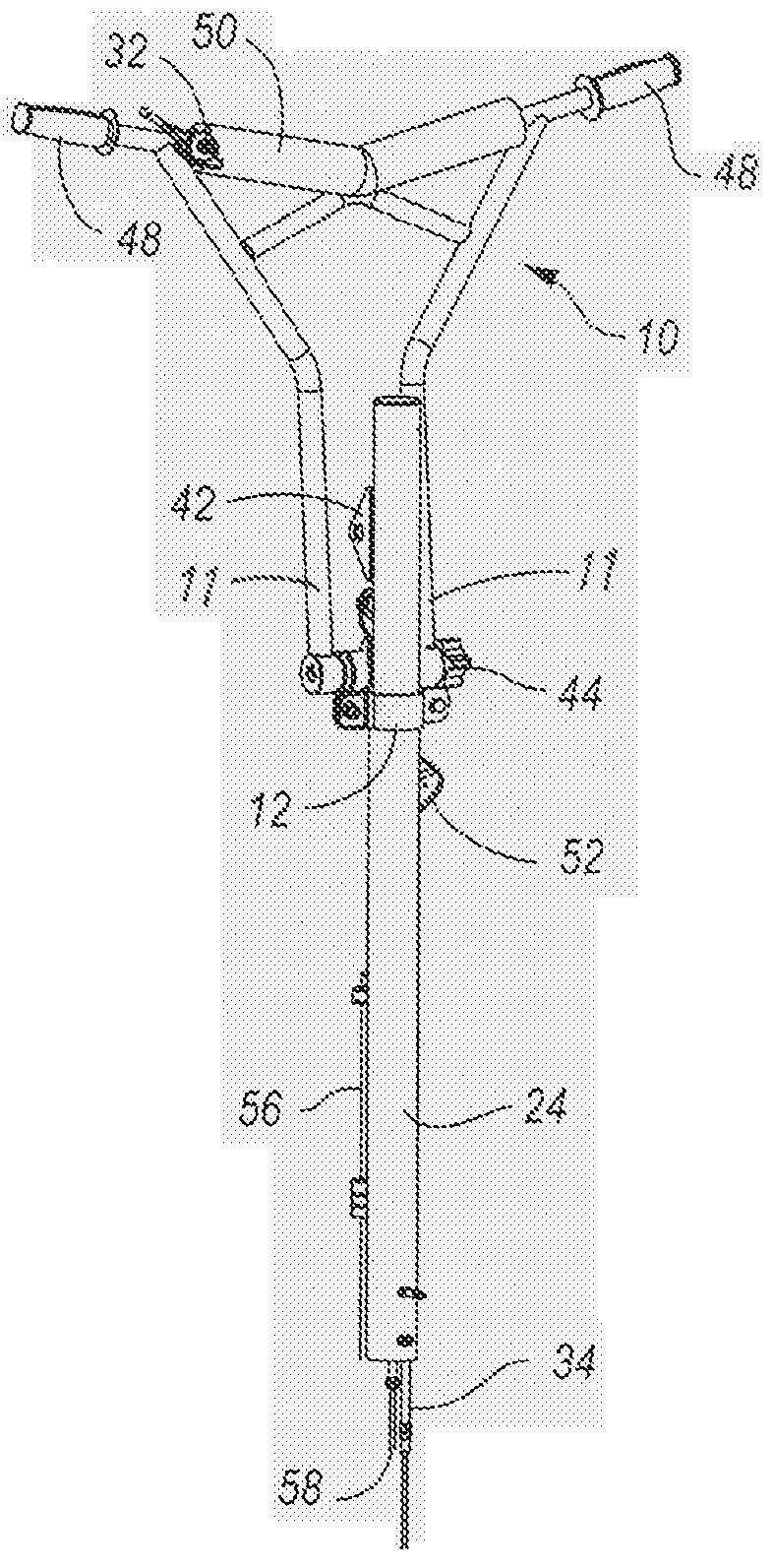
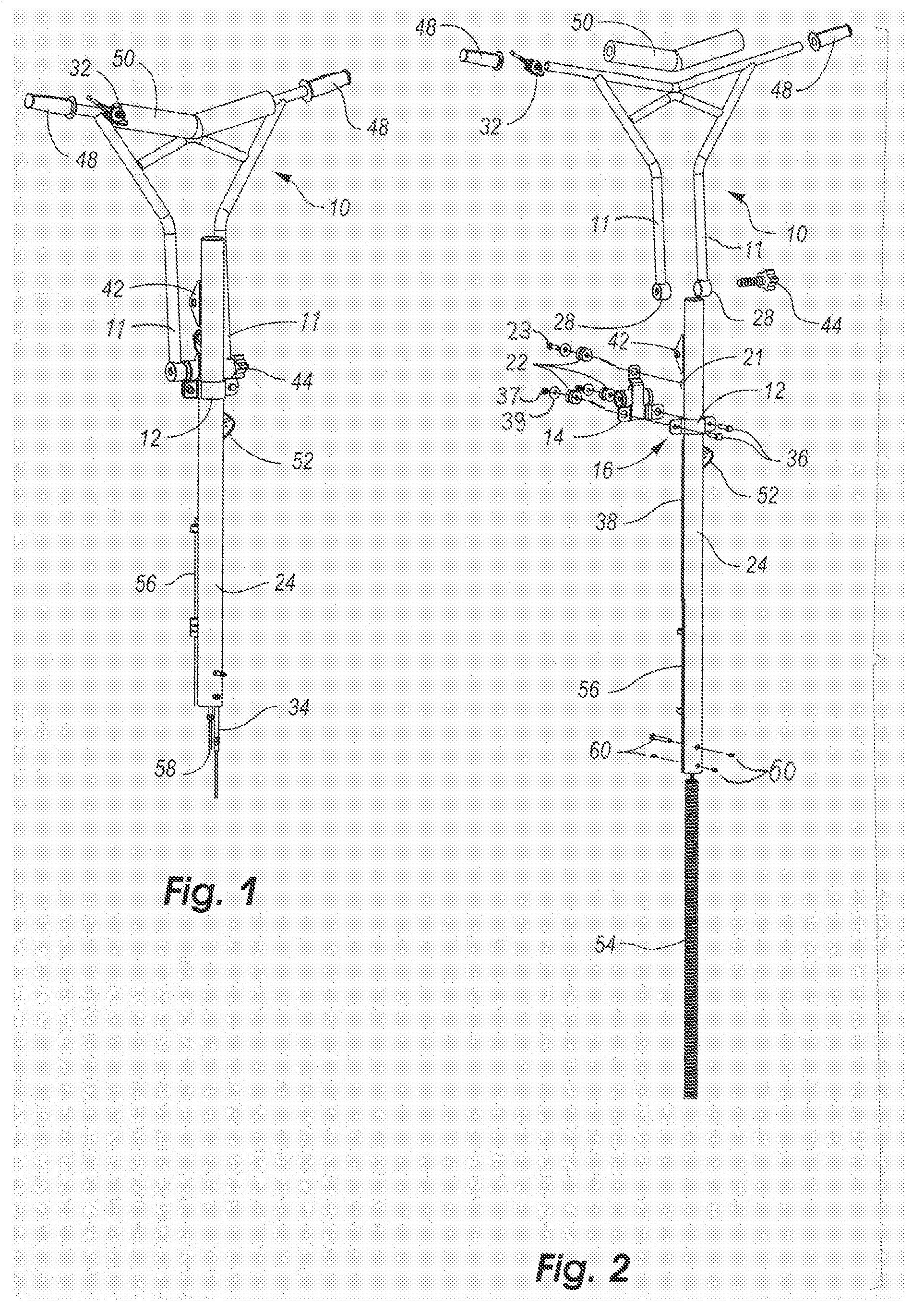
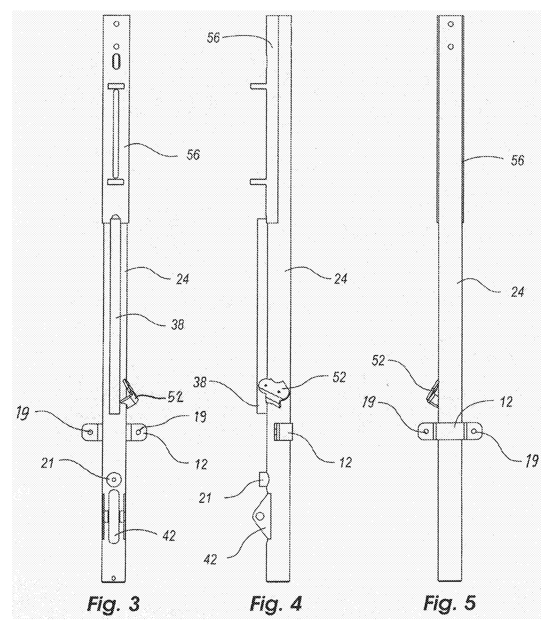
[0022]As shown in the figures for purposes of illustration, the device is embodied in a novel power tool handle that provides vibration dampening while retaining control and stability and makes use of a vibration node point for connecting the frame member to the handle assembly.

[0023]In the following description and in the figures, like elements are identified with like reference numerals. The use of “or” indicates a non-exclusive alternative without limitation unless otherwise no...


PUM


Abstract

Disclosed is a vibration dampening handle for power tools. It includes a frame member attached to the power tool itself, and a handle assembly, which is attached to the frame member via connection to resilient material attached to an isolator chassis assembly located at a vibration node point of the frame member. The vibration dampening handle may also include a height adjustment mechanism.

Description

FIELD OF THE INVENTION[0001]The present invention generally relates to a vibration control handle for use on power tools, and more particularly to a vibration control handle having a vibration dampening connection to a main tool handle, such as the main handle of a walk-behind power trowel.BACKGROUND OF THE INVENTION[0002]Power tools are often operated through a handle assembly that extends from the operator's hands at a standing height to the main body of the tool at the floor or ground level. Such tools may comprise tools for finishing wet cement, cutting dried cement, polishing wood floors, or sanding wood floors. These tools impart considerable vibrations through the handle to the operator's hands and arms. Such vibration transmissions are uncomfortable nuisances that potentially cause fatigue, stress, and injuries.[0003]Prior attempts to dampen vibrations typically relied on use of a dampening system attached to a frame member with a resilient material allowing partial dissipat...

Claims


Application Information

Patent Timeline
IPC IPC(8): B25D17/04
CPCB25F5/006E04F21/24E04F21/248
Inventor CHAPPLE, LARRY JAKEPRAIRIE, DOUGLAS SAMUEL
Owner CHAPPLE LARRY JAKE
Why Eureka
Try Eureka