
Bolt Lock For Saw Blades

a technology of bolt lock and saw blade, which is applied in the direction of threaded fasteners, screwdrivers, manufacturing tools, etc., can solve the problems of bolts that have the potential to loosen, fail to realize the importance of proper torque, and the bolt has the potential to become loos

Inactive Publication Date: 2008-11-27
DIAMOND PROD
View PDF23 Cites 95 Cited by
  • Summary
  • Abstract
  • Description
  • Claims
  • Application Information

AI Technical Summary

Problems solved by technology

Incidents can occur in which the mounting bolt becomes loose, resulting in damage.
If a blade becomes loose from a concrete saw it has the potential to be a problem.
If a saw operator fails to sufficiently tighten the mounting bolt holding the blade collar properly or the threads are worn, the bolt has the potential to become loose.
Operators of concrete saws have a tendency to approach this casually and fail to realize the importance of proper torque when tightening the mounting bolt holding the blade collar in place.
Another reason for failure of engagement of the blade stems from inadequate operator training.
Even if supervisors have been sufficiently trained, workers in the field may not receive such training.
Or, training efforts are not always continued so that after a period of time, new workers receive inadequate training or none at all.
Another reason for failure of blade engagement is that users fail to apply the 125 to 150 foot-pounds of torque suggested for tightening the mounting bolt.
Yet another reason for failure of blade engagement is that the split lock washers that some manufacturers provide with concrete saws are not replaced on a regular basis.
Moreover, another reason for failure of blade engagement relates to operators not removing blade guards when replacing blades.
While this may save time, it makes it difficult if not impossible to tighten the mounting bolt holding the collar, particularly using an open ended wrench supplied by many manufacturers.

Method used


Image

  • Bolt Lock For Saw Blades
  • Bolt Lock For Saw Blades
  • Bolt Lock For Saw Blades

Examples


Embodiment Construction

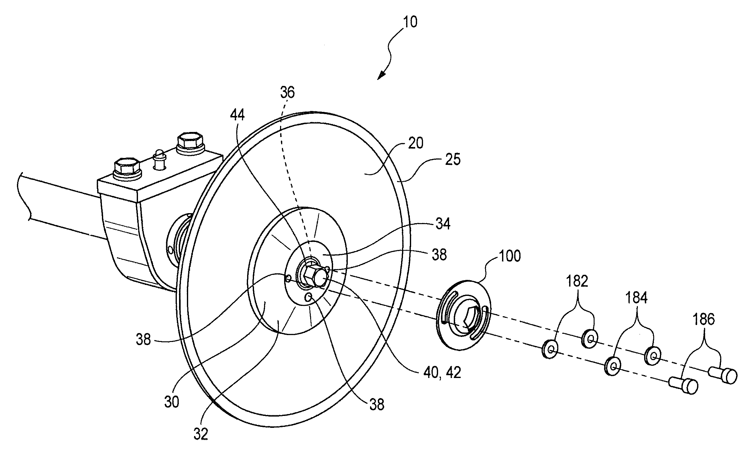
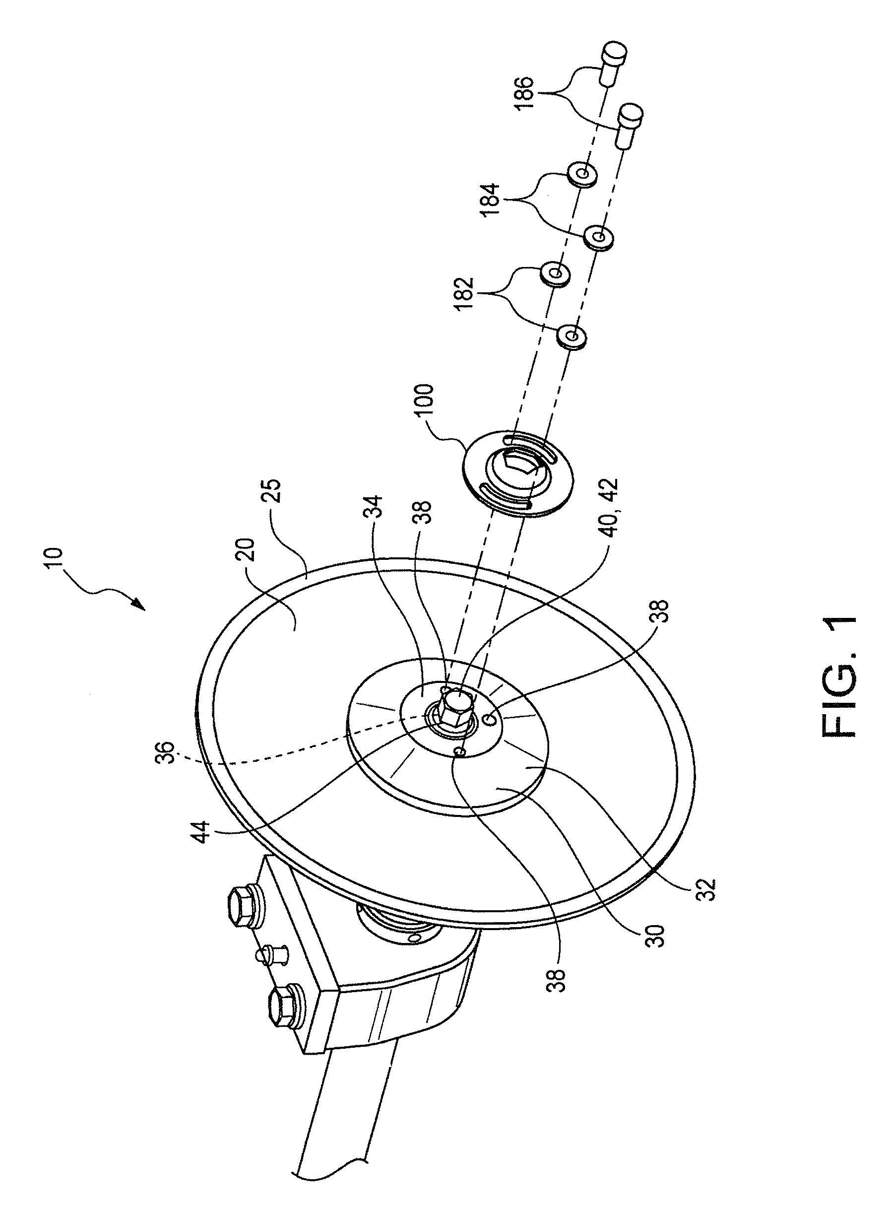
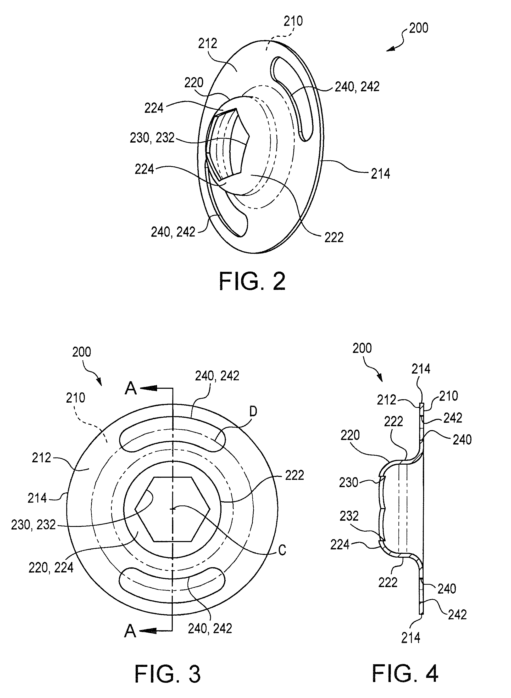
[0026]In accordance with the present invention, a bolt lock and associated assembly are provided. Preferably, the bolt lock is positioned over a mounting bolt holding a blade collar in place after the mounting bolt has been appropriately tightened. Preferably, the bolt lock defines an opening at the center of the bolt lock that is dimensioned such that it is slightly larger than the head of the mounting bolt. Preferably, a modified blade collar may also be provided in accordance with the present invention. The modified blade collar is preferably altered in two respects. First, the blade collar is modified or otherwise formed, so that a center region of the collar is flat. Secondly, one or more threaded receiving apertures are provided in the collar radially outward from the center of the collar. These threaded apertures receive one or more secondary bolts for securing the bolt lock to the blade collar. These aspects are all described in greater detail herein.

[0027]FIG. 1 is a schema...


PUM

PropertyMeasurementUnit
Shapeaaaaaaaaaa

Abstract

A bolt lock is described for attachment to a blade collar of a concrete saw. The bolt lock stabilizes the position of a blade collar mounting bolt thereby preventing the bolt from loosening, which could otherwise result in the blade disengaging from the concrete saw.

Description

CROSS REFERENCES TO RELATED APPLICATIONS[0001]This application is a continuation-in-part of U.S. application Ser. No. 11 / 950,766 filed Dec. 5, 2007 which claims priority to provisional application Ser. No. 60 / 873,660 filed Dec. 8, 2006, both of which applications are incorporated herein by reference.BACKGROUND OF THE INVENTION[0002]1. Field of the Invention[0003]The present invention relates to a bolt lock for attachment to a blade collar typically used in a saw utilizing a circular blade. In particular, the bolt lock stabilizes the position of a blade collar bolt which secures the blade collar and blade in a typical concrete saw.[0004]2. Description of Related Art[0005]Concrete saws typically use a circular blade having a cutting edge formed along the perimeter or peripheral edge of the blade. The blade is engaged to a powered rotating shaft by a blade collar. The blade is rotated at relatively high speeds and used in either wet or dry applications as desired.[0006]The blade collar...

Claims


Application Information

Patent Timeline
IPC IPC(8): B26D7/26
CPCB27B5/32F16B39/10Y10T83/9464
Inventor ASTON, JAMES
Owner DIAMOND PROD
Learn More