
Angiography device and associated recording method with a mechanism for collision avoidance

a technology of collision avoidance and recording method, which is applied in the field of angiography device, can solve the problems of no alternative to angiography, no longer active collision computer, and doctor's inability to intervene, so as to improve patient protection

Active Publication Date: 2008-11-13
SIEMENS HEALTHCARE GMBH
View PDF5 Cites 19 Cited by
  • Summary
  • Abstract
  • Description
  • Claims
  • Application Information

AI Technical Summary

Benefits of technology

[0009]Based on the preceding, discussed disadvantages and problems, the invention addresses the object of further developing an angiography system such that unplanned and unintentional movements of the patient during his / her examination can be detected by the system in real-time, and in the event of a risk of the patient colliding with the C-arm, the movement of the C-arm or of the patient table stops immediately without the system first having to come to a stop, in a type of “emergency stop”, by means of the electromechanical driving switch. To reduce the movement artifacts and shorten the examination times, higher speeds of the C-arm are needed in the future, as a result of which a dynamic mechanism for collision avoidance is necessary in order to protect the patient.
[0011]The present invention is advantageous for the following reason. Prior to the actual examination, the real outer dimensions of the patient are determined as the individual static envelope. During the actual examination, the real outer dimensions of the patient are determined in real-time as the dynamic envelope. The angiography device and in particular the C-arm or the patient table stops if the distance from individual static to dynamic envelopes exceeds an adjustable value for a position of the C-arm or patient table. This provides for a considerably improved protection of the patient from collisions with the C-arm of the angiography device, in comparison with the prior art, in the event of the patient moving beyond a certain threshold during the examination. In addition, the determination and use of individual static envelopes allows the C-arm to be moved very close to the patient during the actual examination.

Problems solved by technology

With interventions, i.e. if the examination achieves in making a narrowing of a vessel visible, in order to extend this and / or keep it open using a stent, there are currently no alternatives to angiography.
In this way, the collision computer is no longer active and the doctor is also no longer able to intervene.
If a collision is impending, the system inhibits the movement of the patient positioning system.
The problem thus consists in the angiography system described in the prior art not being able to detect a movement of the patient during the examination using x-rays and thus not being able to get sufficiently close to the patient as a result of the large dimensioning of static envelopes of the C-arm at many points.

Method used


Image

  • Angiography device and associated recording method with a mechanism for collision avoidance
  • Angiography device and associated recording method with a mechanism for collision avoidance

Examples


first embodiment

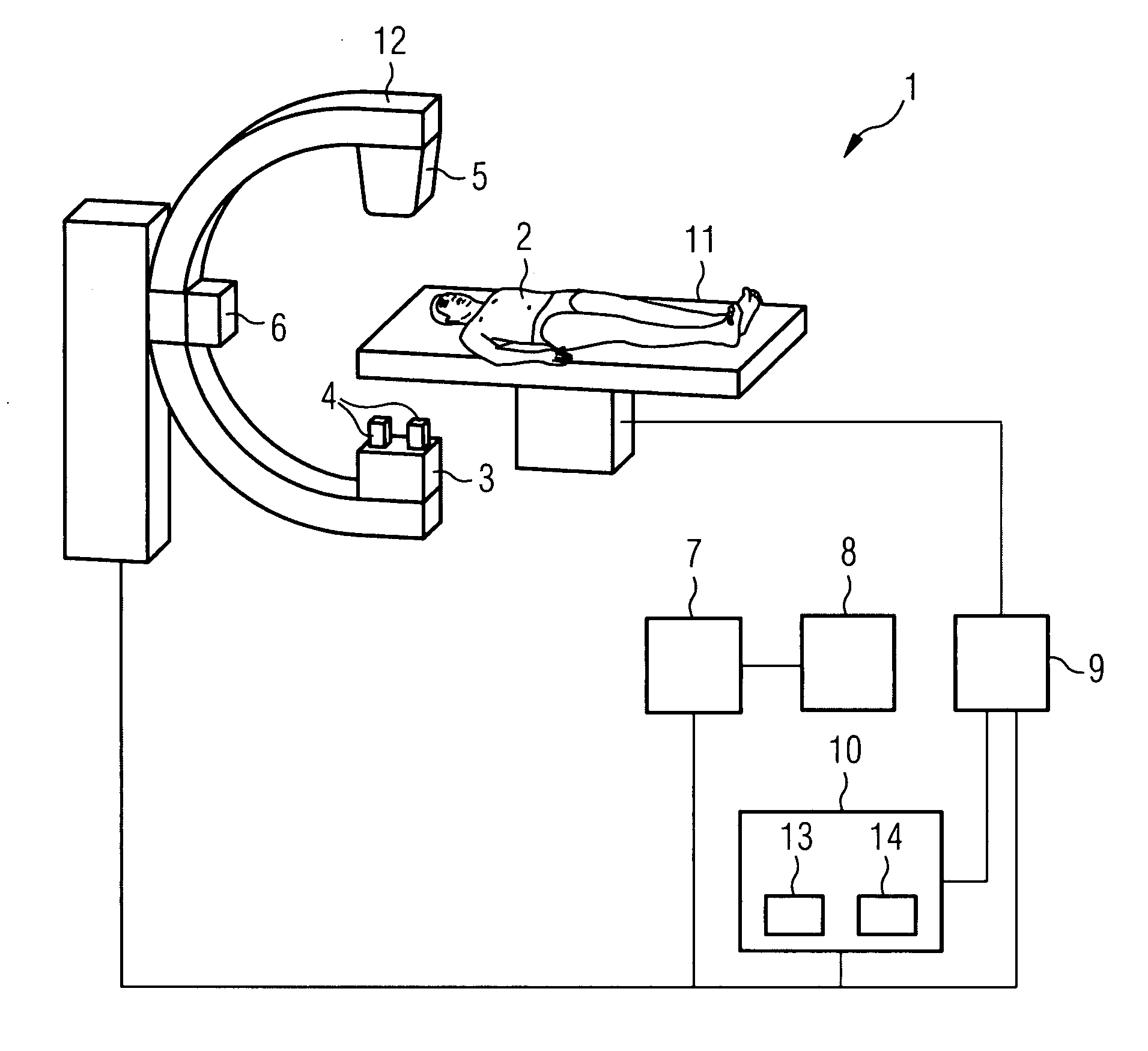
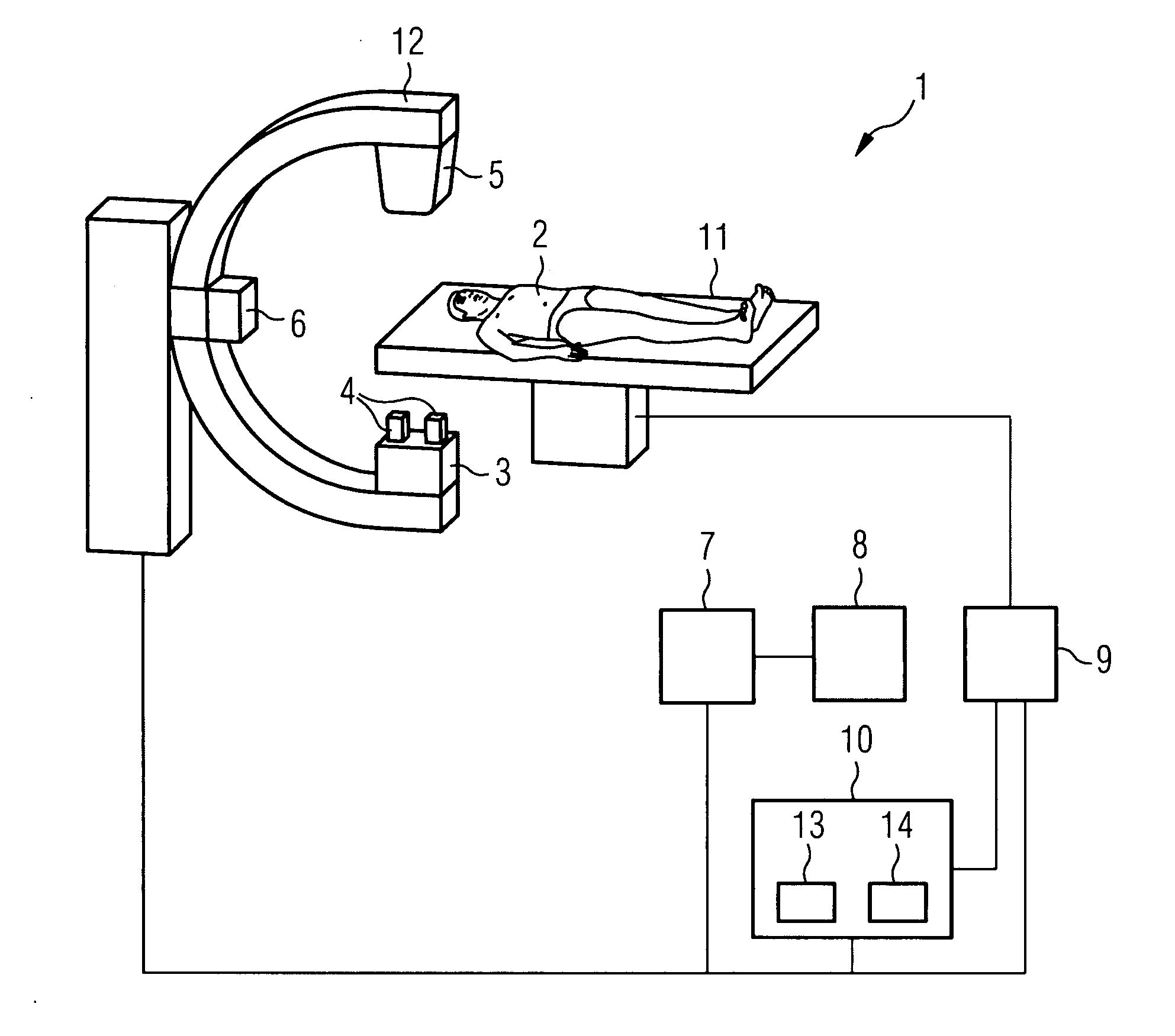
[0016]A first embodiment involves a system with a C-arm 12 and a patient table 11, with the emitter 3, diaphragm 4, detector 5 and sensors 6 being attached to the C-arm 12 and the C-arm 12 being rotatable or alternatively longitudinally moveable along the longitudinal axis of the patient table 11.

second embodiment

[0017]A second embodiment involves a system with a C-arm 12 and a patient table 11, with the emitter 3, diaphragm 4, detector 5 and sensors 6 being attached to the C-arm 12 and with the patient table 11 being longitudinally moveable along its longitudinal axis.

[0018]The above cited sensors 6 for the contactless distance measurement can be capacitive proximity sensors and / or ultrasound sensors and / or laser systems and / or camera systems and they can be attached to the C-arm 12 and / or the attachment components of the C-arm 12 such that the distance of the system from the patient 2 can be measured at every position of the C-arm 12 or of the patient table 11, and a patient envelope can be determined. The sensors 6 can be attached along the C-arm 12, preferably in the center of the C-arm 12 and / or on the detector 5 and / or on the diaphragm 4. The C-arm 12 can rotate about the isocenter and the rotational speed can amount here to 100 degrees per second or more.

[0019]The sensor data of the i...


PUM


Abstract

The present invention involves an angiography device for examining vessels of patients having an x-ray emitter and an associated detector, having an image processing unit, an image display unit, a control unit, a collision computer and sensors. The sensors, which are fastened to the angiography device, are designed to scan the outer dimensions of the patient prior to the actual examination and during the examination. The data obtained in this way can be fed into a memory of the collision computer and the system is controllable by a software of the collision computer such that the movement of the system when the system and patient become too close can be automatically slowed down or completely stopped by means of a the control unit.

Description

CROSS REFERENCE TO RELATED APPLICATIONS[0001]This application claims priority of German application No. 10 2007 021 769.4 filed May 9, 2007, which is incorporated by reference herein in its entirety.FIELD OF THE INVENTION[0002]The present invention relates to an angiography device having an x-ray emitter, detector, image processing unit, image display unit, control unit, collision computer and sensors and an associated angiography method for the examination of the vessels of patientsBACKGROUND OF THE INVENTION[0003]X-ray systems are nowadays to be assigned mostly in a dedicated fashion to a clinical application field. A distinction is thus made between angiography systems, fluoroscopy systems and radiography systems. In this classification, the two first-mentioned system groups can cover both dynamic applications as well as also single shots. Angiography, sonography, computer tomography, magnetic resonance tomography and optical coherence tomography are primarily available for the e...

Claims


Application Information

Patent Timeline
Patent Type & Authority Applications(United States)
IPC IPC(8): H05G1/64
CPCA61B6/102A61B6/481A61B6/504
Inventor SATTLER, STEFANSTAAB, REINERSTAAB, SUSANNESTAAB, KATHARINARACHOR, SILVIA
Owner SIEMENS HEALTHCARE GMBH
Learn More