
Liquid crystal display device

a liquid crystal display and liquid crystal technology, applied in static indicating devices, non-linear optics, instruments, etc., can solve the problems of difficult to effectively suppress display defects, display non-uniformity, and ions spreading into the display region, etc., to achieve high display quality, high reliability, and suppress display defects

Inactive Publication Date: 2008-11-13
JAPAN DISPLAY CENTRAL CO LTD
View PDF2 Cites 19 Cited by
  • Summary
  • Abstract
  • Description
  • Claims
  • Application Information

AI Technical Summary

Benefits of technology

[0014]The present invention has been made in consideration of the above-described problems, and the object of the invention is to provide a liquid crystal display device which can suppress a display defect, such as display non-uniformity, due to non-uniformity of ions in a liquid crystal layer, and has high display quality and high reliability.
[0017]The present invention can provide a liquid crystal display device which can suppress a display defect, such as display non-uniformity, due to non-uniformity of ions in a liquid crystal layer, and has high display quality and high reliability.

Problems solved by technology

In the above-described prior art invention, however, no consideration is given to the rubbing direction of alignment films, and it is difficult to effectively suppress a display defect due to ions which move in the rubbing direction.
In particular, in a liquid crystal display panel with a small picture-frame region surrounding the display section, the picture-frame region is small, compared to the amount of ions in the entire liquid crystal display panel, thus leading to a case in which ions spreads into the display region due to long-time driving.
In particular, the transmittance versus application voltage characteristics of the liquid crystal layer vary in the display section, and such a variation, in some cases, may be recognized as display non-uniformity.

Method used


Image

  • Liquid crystal display device
  • Liquid crystal display device
  • Liquid crystal display device

Examples


first embodiment

[0035]A liquid crystal display device according to the present invention will now be described with reference to the accompanying drawings. The liquid crystal display device according to the present embodiment is, for instance, an OCB mode liquid crystal display device which includes a liquid crystal display panel PNL. The liquid crystal display panel PNL includes an array substrate (not shown), a counter-substrate (not shown), and a liquid crystal layer LQ which is held between the array substrate and the counter-substrate.

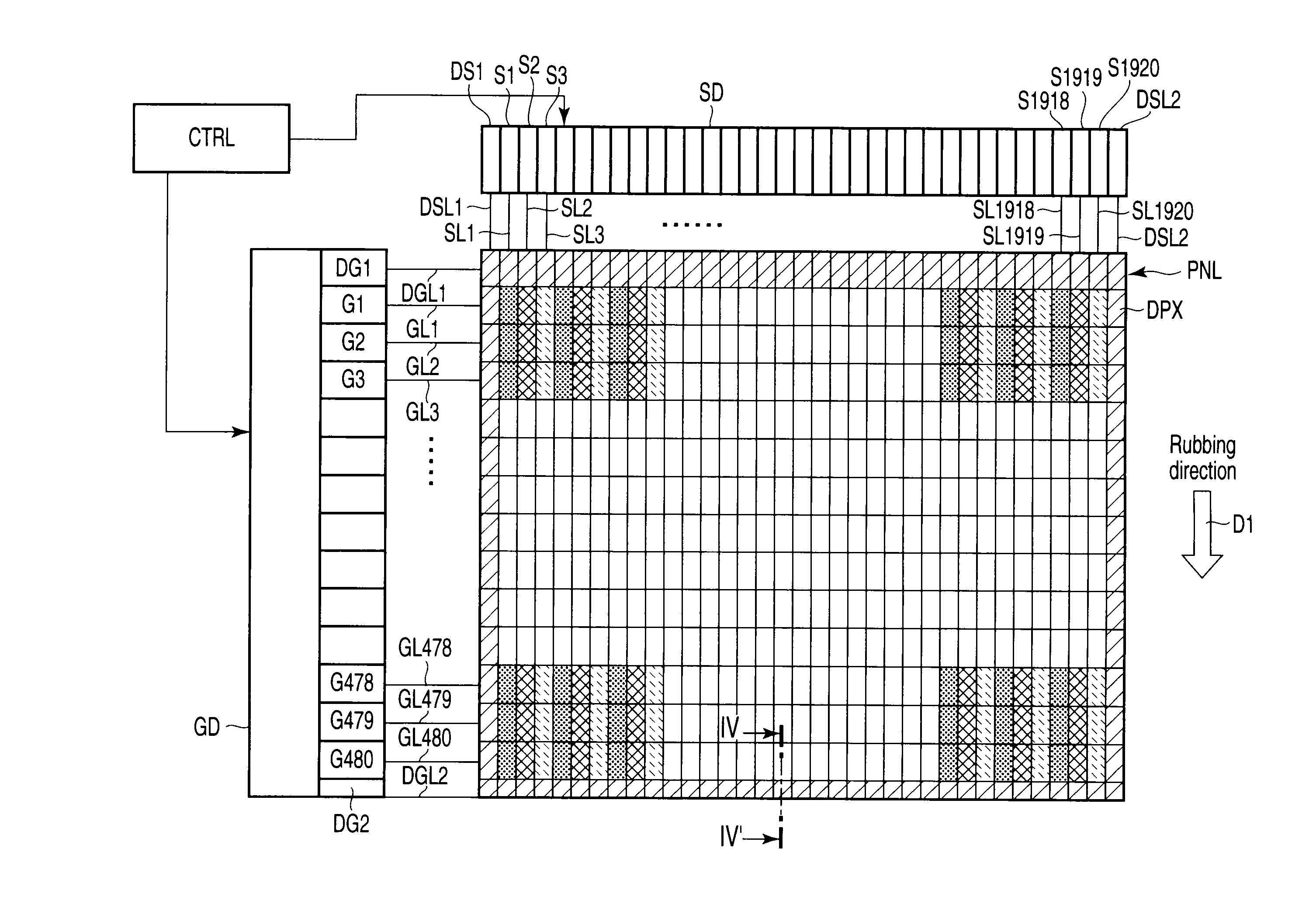
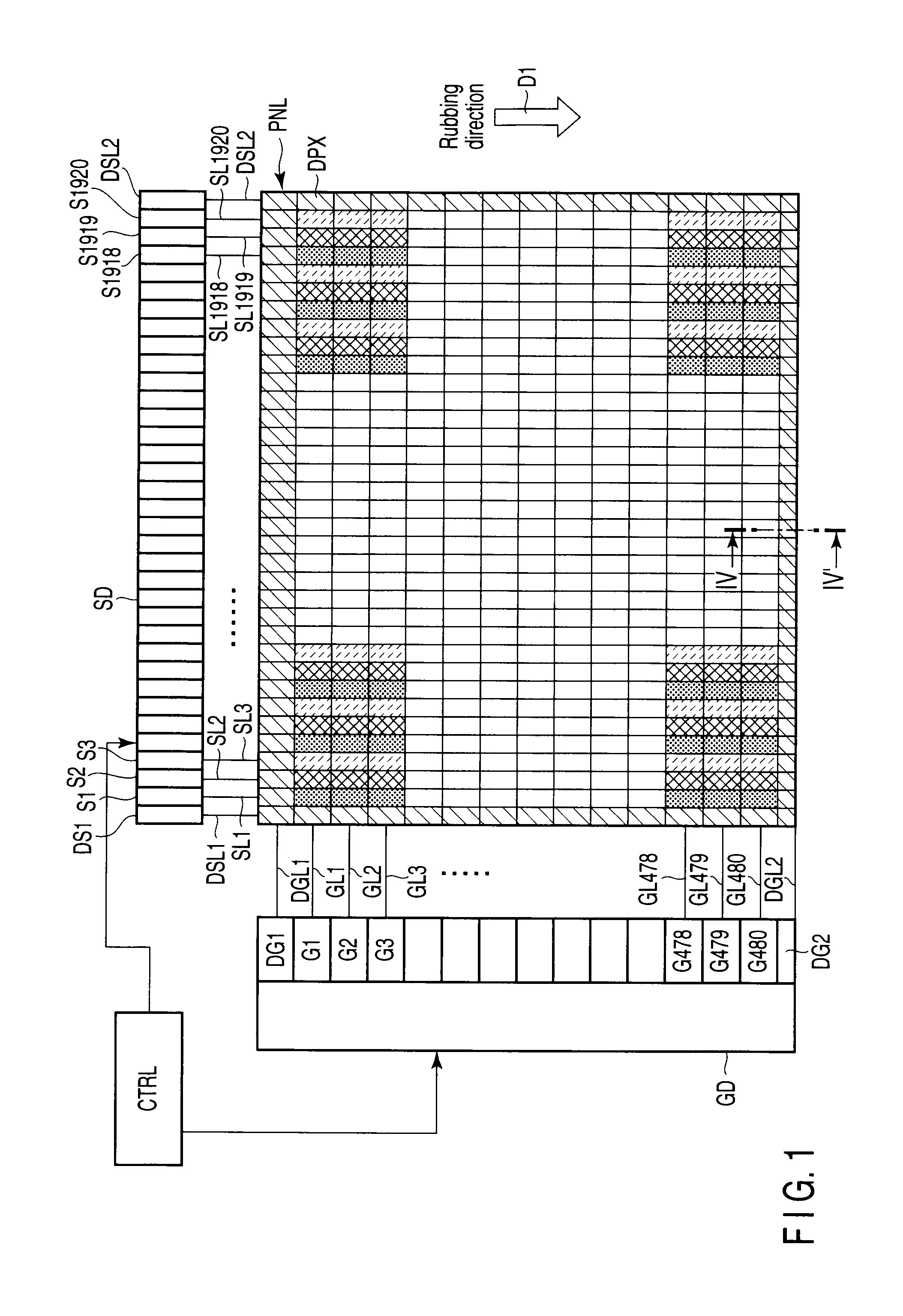
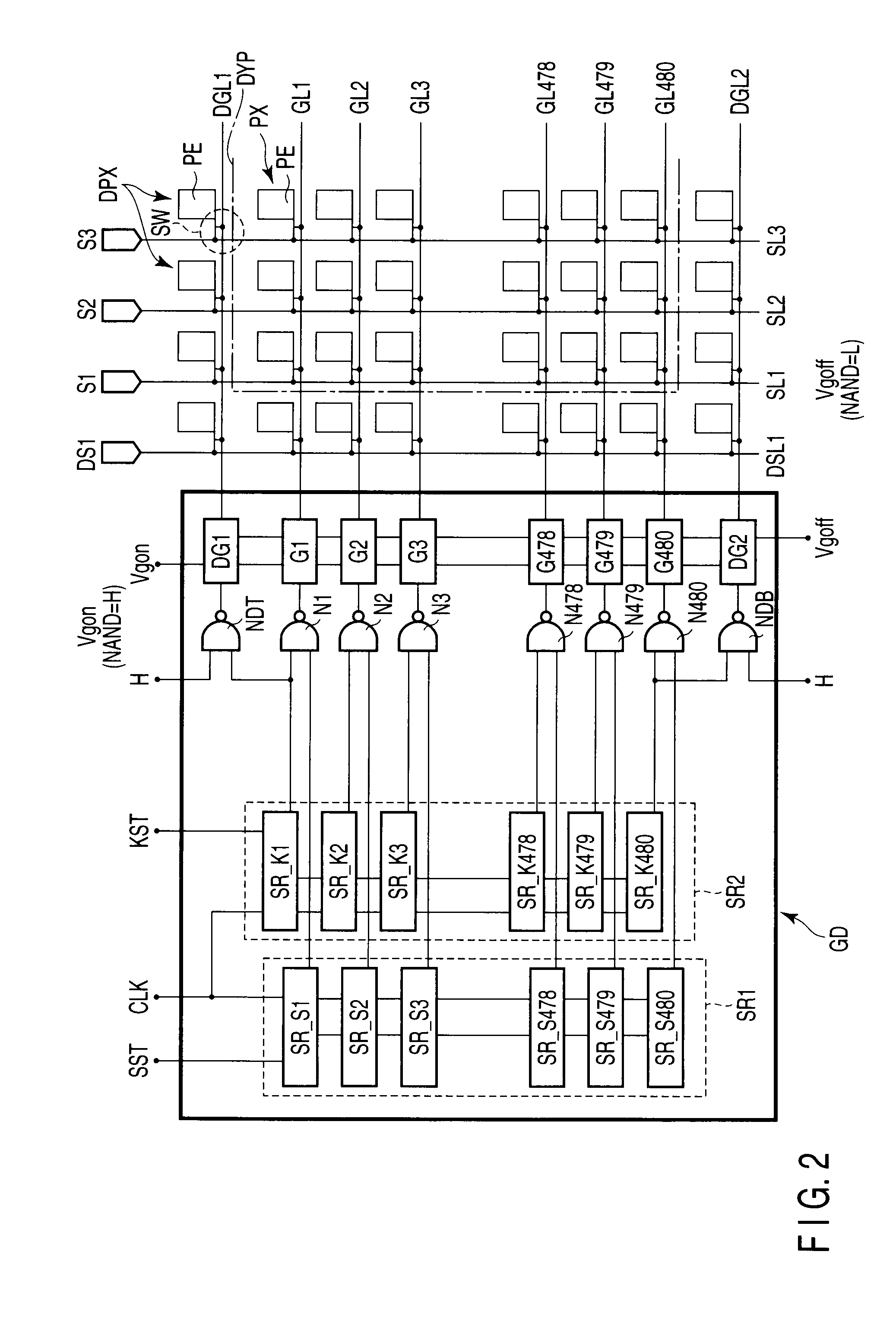
[0036]As shown in FIG. 1, the liquid crystal display panel PNL includes a display section DYP which is composed of display pixels PX arrayed in a matrix, and dummy display pixels DPX which are so arranged as to surround the display section DYP. In a color-display-type liquid crystal display device, various kinds of display pixels, such as a red display pixel, a green display pixel and a blue display pixel, are disposed as the display pixels PX in the display sect...

fourth embodiment

[0082]Next, a liquid crystal display device according to the present invention is described with reference to the accompanying drawings. As shown in FIG. 1 and FIG. 10, a liquid crystal display panel 10 of the liquid crystal display device according to the present embodiment has a substantially rectangular shape, and includes a display section DYP which is composed of a plurality of display pixels PX arrayed in a matrix, and a peripheral section 10B surrounding the periphery of the display section DYP. In a color-display-type liquid crystal display device, various kinds of display pixels, such as a red display pixel, a green display pixel and a blue display pixel, are disposed as the display pixels PX in the display section DYP.

[0083]An array substrate 12 includes a plurality of pixel electrodes PE which are disposed substantially in a matrix in association with the display pixels PX. A counter-substrate 14 includes a counter-electrode CE which is opposed to the plural pixel electro...


PUM

PropertyMeasurementUnit
shapeaaaaaaaaaa
fixed voltageaaaaaaaaaa
voltageaaaaaaaaaa

Abstract

A liquid crystal display device includes a liquid crystal display panel having a display section which is composed of a plurality of display pixels, a driving unit which drives the display pixels, and a control unit which controls the driving unit. A first substrate includes pixel electrodes which are disposed in association with the plurality of display pixels. A second substrate includes a counter-electrode which is opposed to the plurality of pixel electrodes. A pair of alignment films are disposed on the plurality of pixel electrodes and the counter-electrode, and control an alignment state of liquid crystal molecules, which are included in the liquid crystal layer, by rubbing treatment. Dummy display pixels are disposed on a terminal end side of the display section in a rubbing direction. A driving unit includes circuit for cyclically applying a reverse transition prevention signal to the dummy display pixels.

Description

CROSS-REFERENCE TO RELATED APPLICATIONS[0001]This application is based upon and claims the benefit of priority from prior Japanese Patent Applications No. 2007-123721, filed May 8, 2007; and No. 2007-165551, filed Jun. 22, 2007, the entire contents of both of which are incorporated herein by reference.BACKGROUND OF THE INVENTION[0002]1. Field of the Invention[0003]The present invention relates generally to a liquid crystal display device and more particularly to an active matrix liquid crystal display device.[0004]2. Description of the Related Art[0005]In general, a liquid crystal display device includes a liquid crystal display panel having a display section on which an image is displayed. The liquid crystal display panel includes a pair of mutually opposed substrates. A liquid crystal layer is held between the pair of substrates.[0006]One of the substrates includes a plurality of pixel electrodes which are arrayed substantially in a matrix. The other substrate includes a counter-e...

Claims


Application Information

Patent Timeline
Patent Type & Authority Applications(United States)
IPC IPC(8): G09G3/36G02F1/133G02F1/1337
CPCG02F1/1395G02F2001/133388G09G3/3648G09G3/3688G09G2300/0491G09G2310/0232G09G2310/06G09G2320/0233G02F1/133388
Inventor FUKAMI, TETSUOTANAKA, YUKIOMIYATAKE, MASAKIAZUMA, HIROSHINAKAO, KENJI
Owner JAPAN DISPLAY CENTRAL CO LTD
Learn More