
Bone end (epiphysis) fracture fixation device and method of use

a technology for repairing the epiphysis and the bone end, which is applied in the field of bone end (epiphysis) fracture fixing devices and methods of use, can solve the problem that the art device possess virtually no means for adjusting a particular devi

Inactive Publication Date: 2008-11-06
HAIDUKEWYCH GEORGE J
View PDF19 Cites 16 Cited by
  • Summary
  • Abstract
  • Description
  • Claims
  • Application Information

AI Technical Summary

Benefits of technology

[0010]The invention accordingly comprises the features of construction, combination of elements, and arrangement of parts which will be exemplified in the constructions hereinafter set forth, as well

Problems solved by technology

Just as apparent is the fact that these prior art devices possess virtually no means for adjusting a particular device to the needs of a particular patient.

Method used


Image

  • Bone end (epiphysis) fracture fixation device and method of use
  • Bone end (epiphysis) fracture fixation device and method of use
  • Bone end (epiphysis) fracture fixation device and method of use

Examples

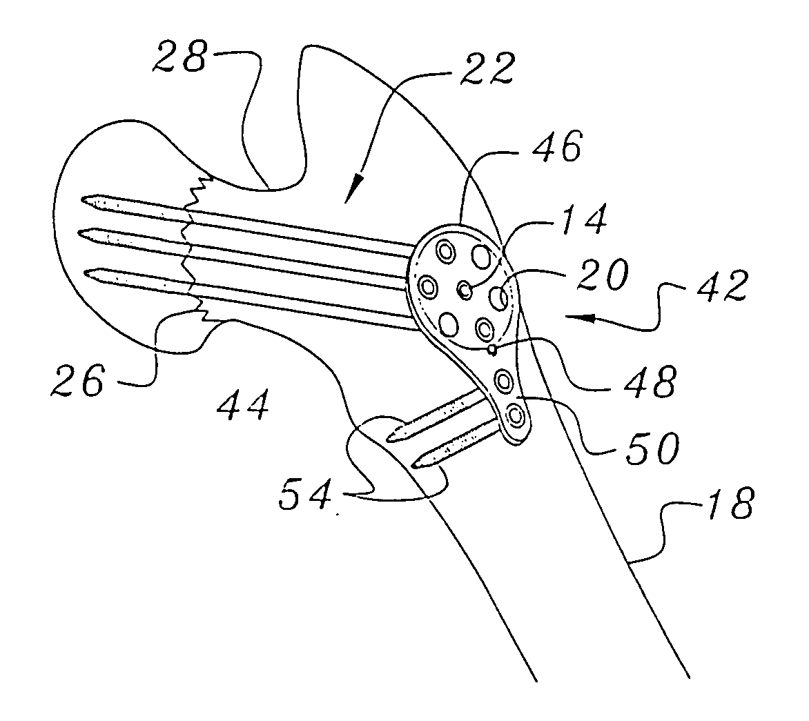

embodiment 10

[0027]Attention is now invited to the views of FIGS. 6 and 7. These figures show a second preferred embodiment for the femoral neck fracture fixation device of this invention, generally indicated as 42. However, structural elements that are substantially identical to those described previously with regard to first preferred embodiment 10 are indicated by like reference numerals.

[0028]As clearly seen in the views of FIGS. 6 and 7. second preferred embodiment 42 comprises not only a fixation plate 12, but also a side plate generally indicated as 44. Fixation plate 12 of second preferred embodiment 42 is rotatably attached to enlarged end 46 of side plate 44. The rotational attachment of fixation plate 12 to enlarged end 46 is accomplished, preferably. by a rotatable attachment around guide pin aperture 14. It is also to be understood that enlarged end 46 of side plate 44 is relieved so that guide pin aperture 14 and the plurality of fixation screw apertures 20 extend through fixation ...

embodiment 42

[0029]In both FIG. 6 and FIG. 7, one can also see that the elongated body 50 of side plate 44 comprises a plurality of side plate apertures 52 formed therethrough. With particular regard to the view of FIG. 7, it can be seen that side plate apertures 52 may be used to receive a corresponding side plate screw 54 therethrough and into the patient's femur, when necessary as determined by the surgeon, for the purpose of providing greater stability and strength to the second preferred embodiment 42 used for femoral neck fracture fixation.

[0030]Of course, it is to be understood that second preferred embodiment 42 is not to be limited to the particular geometric configuration shown in the views of FIGS. 6 & 7. In similar fashion, the scope of the present invention is not to be limited by the particular use of three fixation screws 62 or two side plate screws 54. Such specifics are determined by the surgeon after considering the patient's needs.

[0031]Finally, with regard to second preferred...


PUM


Abstract

A bone end (epiphysis) fracture device including a rotatable fixation plate having a guide pin aperture and a plurality of fixation screw apertures formed therethrough. The guide pin aperture is used by a surgeon to position the fixation plate so that one or more fixation screw apertures are properly positioned to receive fixation screws inserted by the surgeon for repairing a bone end fracture. In another embodiment, the fracture fixation device also includes a side plate to which the fixation plate is rotatably attached. This embodiment further includes one or more side plate apertures formed through an elongate extension, whereby the fixation device may also be attached to the bone for which an end fracture is being repaired. A lock screw is provided in this embodiment for locking the position of the fixation plate with respect to the side plate.

Description

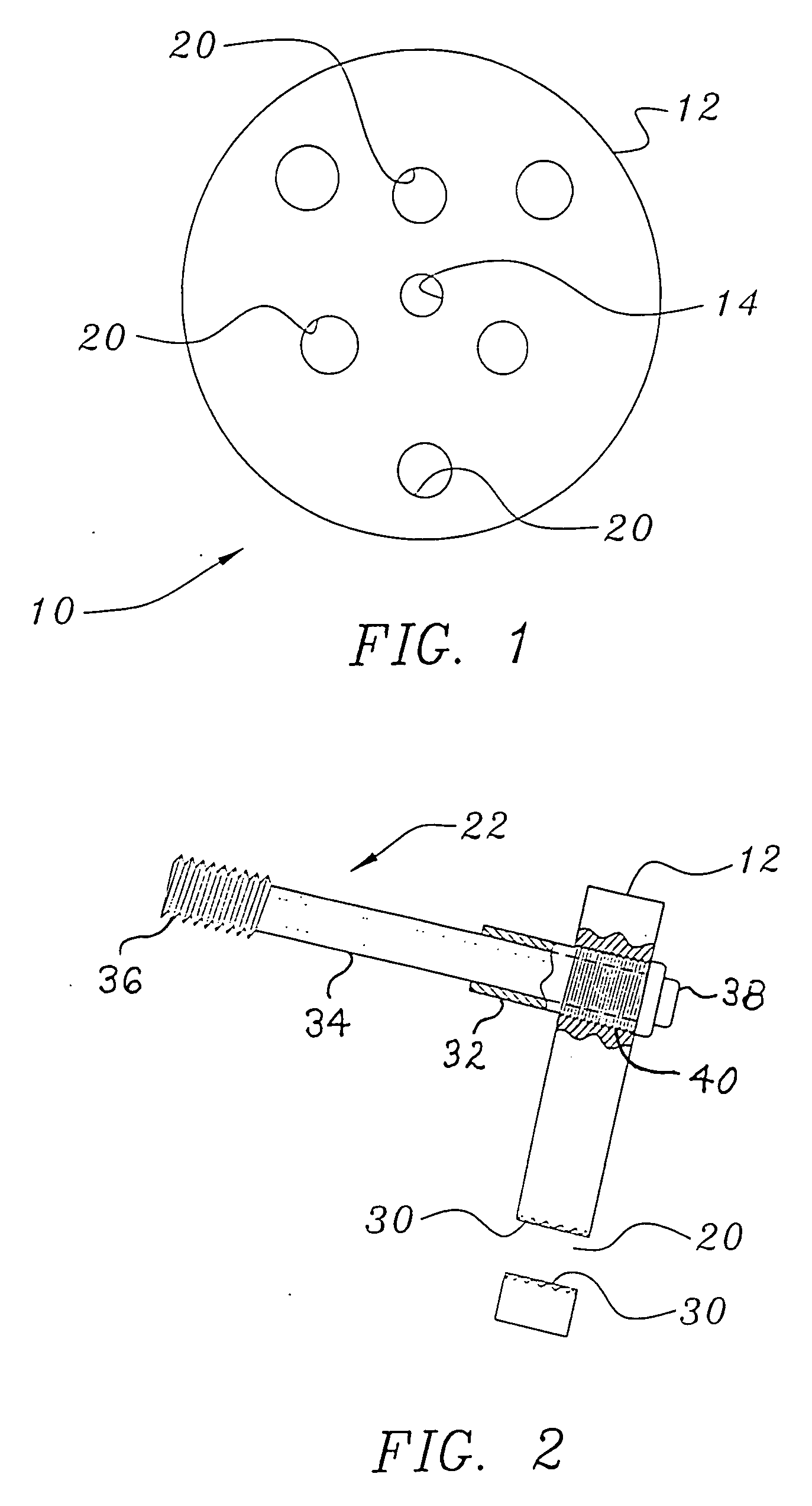
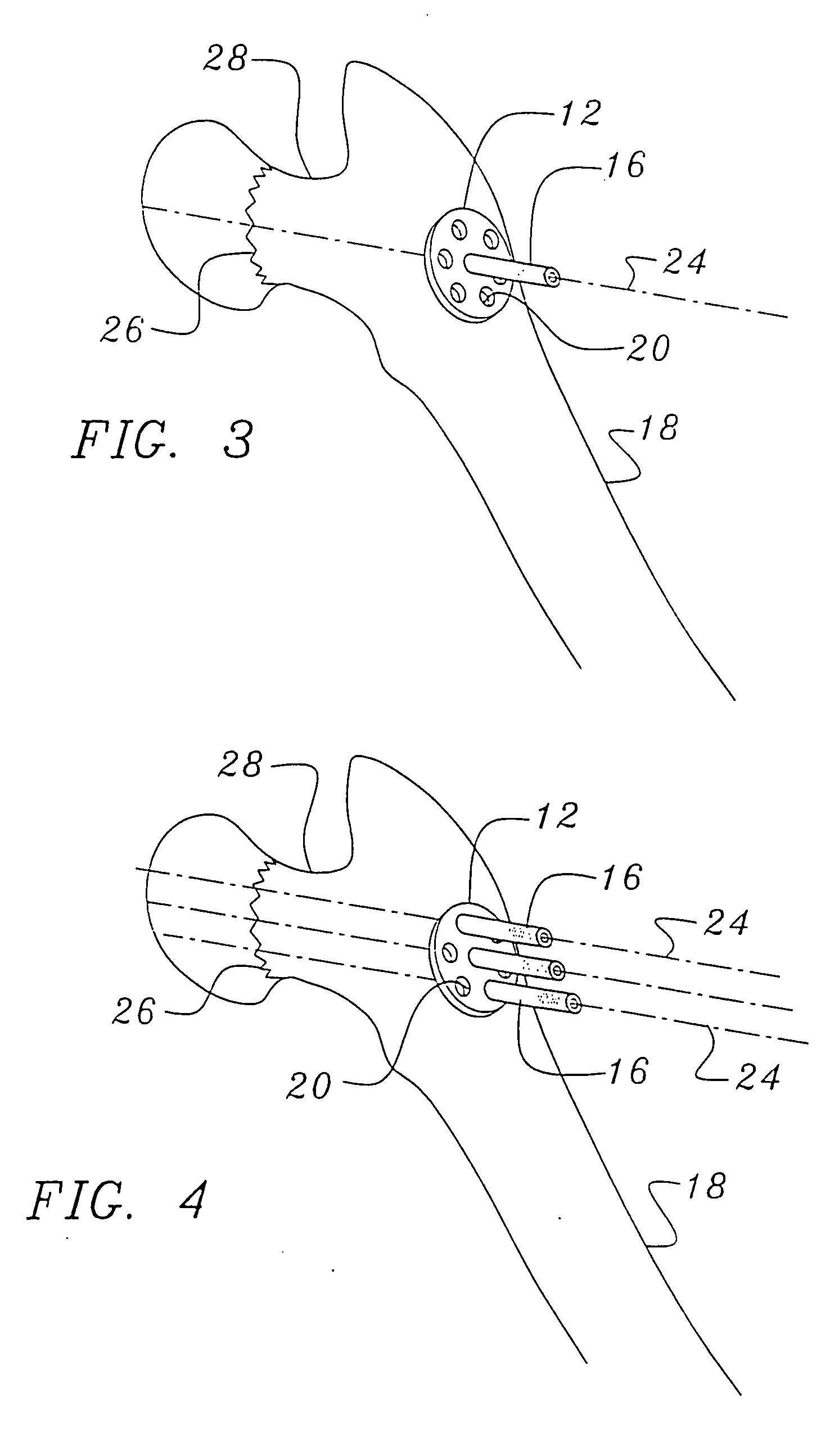
PRIORITY CLAIMING[0001]Applicant claims the benefit of his prior Provisional Application, Ser. No. 60 / 927,667, filed May 4, 2007, and titled FEMORAL NECK FRACTURE FIXATION DEVICE AND METHOD OF USE.BACKGROUND OF THE INVENTION[0002]1. Field of the Invention[0003]The present invention relates to an improved fixation device for fractures of the ends of bones (epiphysis), and is described in a preferred embodiment with respect to a femoral neck fracture, and its method of use is also disclosed.[0004]2. Description of the Prior Art[0005]The use of various plates and bone screws for fixing bone fractures is old and well known in the art. In fact, prior art patents teach numerous devices for fixing a fracture of bone ends such as the femoral neck. For example, U.S. Patent Application Publication No. US 2006 / 0217711 to Stevens. et al., discloses a locking plate that extends along the length of the femur and provides apertures for inserting a plurality of bone anchor screws into the femoral h...

Claims


Application Information

Patent Timeline
IPC IPC(8): A61B17/70A61B17/56A61B17/58
CPCA61B17/746A61B17/748
Inventor HAIDUKEWYCH, GEORGE J.
Owner HAIDUKEWYCH GEORGE J
Learn More