
Autonomous continuous atmospheric present weather, nowcasting, and forecasting system

a forecasting system and atmospheric present weather technology, applied in the direction of optical radiation measurement, instruments, heat measurement, etc., can solve the problems of high front-end, operating, maintenance and repair costs, high power consumption of radars, lidars, other atmospheric sensor systems, etc., to complement or augment the system's skill, enhance the interpretation skill, and improve the effect of the skill

Inactive Publication Date: 2008-10-30
SOLHEIM HUNTER +1
View PDF3 Cites 39 Cited by
  • Summary
  • Abstract
  • Description
  • Claims
  • Application Information

AI Technical Summary

Benefits of technology

[0020]It is another embodiment of this invention to provide apparatus and method to include other ancillary data sources in concert such as weather models, weather forecasts, satellite, GPS refractivity and water vapor, LIDAR, FTIRs, aircraft borne sensors, lower boundary layer in situ, climatological, diurnal and seasonal effects, and/or other such observations and information to augment and improve t

Problems solved by technology

It is a problem in the field of atmospheric meteorological and other parameter measurement to passively, remotely, inexpensively, and continuously measure these parameters.
Active remote sensing systems emit often objectionable or unacceptable radio or light energy and are power consumptive.
Front-end, operating, and maintenance and repair costs can be high.
Radars, LIDARs, and other atmospheric sensor systems are power consumptive, are costly, and often are comprised of expensive finite lifetime components.
Operational costs can therefore be high.
Operational weather radars also cannot detect and track very small cloud droplets because the reflected signal is roughly proportional to the 6th power of the droplet diameter.
Radiation emitted by active remote sensing systems is sometimes intrusive, hazardous to health, and in some military and like applications, compromises covertness.

Method used


Image

  • Autonomous continuous atmospheric present weather, nowcasting, and forecasting system
  • Autonomous continuous atmospheric present weather, nowcasting, and forecasting system
  • Autonomous continuous atmospheric present weather, nowcasting, and forecasting system

Examples


Embodiment Construction

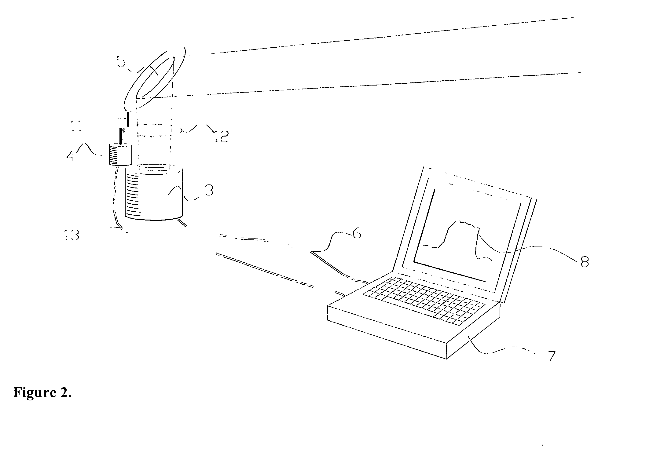
[0030]A first embodiment of an apparatus for passively and remotely locating, monitoring, measuring, and / or predicting certain atmospheric and meteorological parameters is shown in FIG. 1. Infrared emissions 2 originating from an atmospheric feature I are reflected from mirror 5. Mirror 5 is an efficient low loss reflector of infrared such as the Edmund Scientific K32-089 first surface gold mirror or other suitable construction and material. Said emissions are directed by mirror 5 into infrared detector system 4. A suitable infrared detector system is the Raytek Thermalert™ MID™ system, operating in the 8 to 14 micron region, having an angular field of view of about 5 degrees, and outputting analog and digital information relating to the temperature of the object(s) in the field of view. This system consumes about 1 watt of power. This system also conveniently reports surface ambient temperature. Other commercially available noncontact thermometers are the Everest Interscience 4000Z...


PUM


Abstract

Apparatus and methods for passively and remotely and continuously locating, monitoring, and measuring present weather and nowcasting and forecasting weather and meteorological phenomena and parameters by utilizing observations of infrared emissions and reflections are disclosed. Based on observations of an instrument such as an infrared noncontact thermometer, the methods provide useful information on the presence of aerosol, dust, cloud, and precipitation for the purpose of determining present weather, weather tracking, weather nowcasting, and weather forecasting as well as other weather phenomena. One embodiment of this invention is an infrared sensor pointed vertically and reflected from a suitable mirror rotating about a vertical axis such that the field of view of the sensor scans azimuthally at an elevated angle above the horizon.

Description

FIELD OF THE INVENTION[0001]This invention relates to operation and reduction of observations of instruments capable of sensing of certain signatures of atmospheric phenomena. Said signatures can then be interpreted into usable characterization of said atmospheric conditions and phenomena for the purposes of determining present conditions and nowcasting and forecasting weather.BACKGROUND OF THE INVENTION[0002]It is a problem in the field of atmospheric meteorological and other parameter measurement to passively, remotely, inexpensively, and continuously measure these parameters. Active remote sensing systems emit often objectionable or unacceptable radio or light energy and are power consumptive. Front-end, operating, and maintenance and repair costs can be high.[0003]Every substance that is above absolute zero in temperature emits radiation across the entire electromagnetic spectrum in accord with the quantum mechanical Planck function defined in Equation 1 below.I(λ,T)=2πhc2λ5[hc / ...

Claims


Application Information

Patent Timeline
IPC IPC(8): G01W1/00
CPCG01J5/02G01J5/0205G01J5/029G01J5/04G01J5/08G01J5/0809G01K2203/00G01W1/04G01W1/10Y02A90/10G01J5/047G01J5/485G01J5/051G01J5/0808G01J5/07
Inventor SOLHEIM, HUNTERSOLHEIM, FREDRICK
Owner SOLHEIM HUNTER
Learn More