Method and apparatus for use by a patient in temporarily lifting that person with respect to a horizontal surface--such as a bed

a technology for lifting a person and a bed is applied in the field of temporary lifting of a person with respect to a horizontal surface, which can solve the problems of patient losing his or her balance, patient being denied the opportunity to make personal adjustments, and he would be out of luck, so as to achieve less likelihood of imposing an extra burden and positive mental attitud

Inactive Publication Date: 2008-10-30
PASTUSEK JONATHAN EDWARD
View PDF7 Cites 0 Cited by
  • Summary
  • Abstract
  • Description
  • Claims
  • Application Information

AI Technical Summary

Benefits of technology

[0008]In brief, the invention disclosed herein involves a two-stage support for a trapeze or other structure (such as a sling) that depends from a rail, said rail extending over a bed (usually a hospital bed) or other patient-support device. In the first stage of operation, a carriage is provided that permits free and unobstructed movement of the carriage along a conventional rail, from one end to the other. A variety of constructions for the proposed carriage are disclosed, some of which include wheels that bear against the top of the rail to provide low-friction contact with the rail. Other constructions omit wheels but rely strictly on geometry to foster incremental relative movement between the carriage and the rail—when it is desired. In the preferred embodiment of the invention, the carriage is held static in the second stage of operation, such that it provides a stable “anchor” for a trapeze and the person who is pulling downward on the trapeze. This second stage of operation can be initiated by the action of pulling downward on the trapeze, causing the carriage to bear against the rail with what may best be described as a “gripping” action. The switching between free movement along the rail and braked movement can be automatic, and involves only a downwardly directed force on the carriage, which force may be supplied by an attending nurse—or the patient who is to be the beneficiary of any vertical movement with respect to the horizontal bed. By allowing the patient to control the location and use of the trapeze, there will be less likelihood of imposing an extra burden on a busy nurse or other care-giver. That is, a restless patient who never seems to be satisfied and / or comfortable, and who is always wanting to accomplish a change in body position, can perhaps accomplish those desired changes without demanding help from anyone else. And anything that helps develop a positive mental attitude on the part of a patient is considered to be beneficial.

Problems solved by technology

But if a person on the bed wanted to move the trapeze a smaller distance, e.g., ¼ inch, he would be out of luck.
First, the trapeze needs to be held in a static manner—at least during the time when a patient is pulling downward on the trapeze handle, or else the trapeze might slip or even move a short distance horizontally along the rail.
This could cause the patient to lose his or her balance during the course of attempting a lifting maneuver.
In both of these situations, the patient is usually denied the opportunity to make personal adjustments in the physical location of the trapeze along the rail.

Method used


Image

  • Method and apparatus for use by a patient in temporarily lifting that person with respect to a horizontal surface--such as a bed
  • Method and apparatus for use by a patient in temporarily lifting that person with respect to a horizontal surface--such as a bed
  • Method and apparatus for use by a patient in temporarily lifting that person with respect to a horizontal surface--such as a bed

Examples


Embodiment Construction

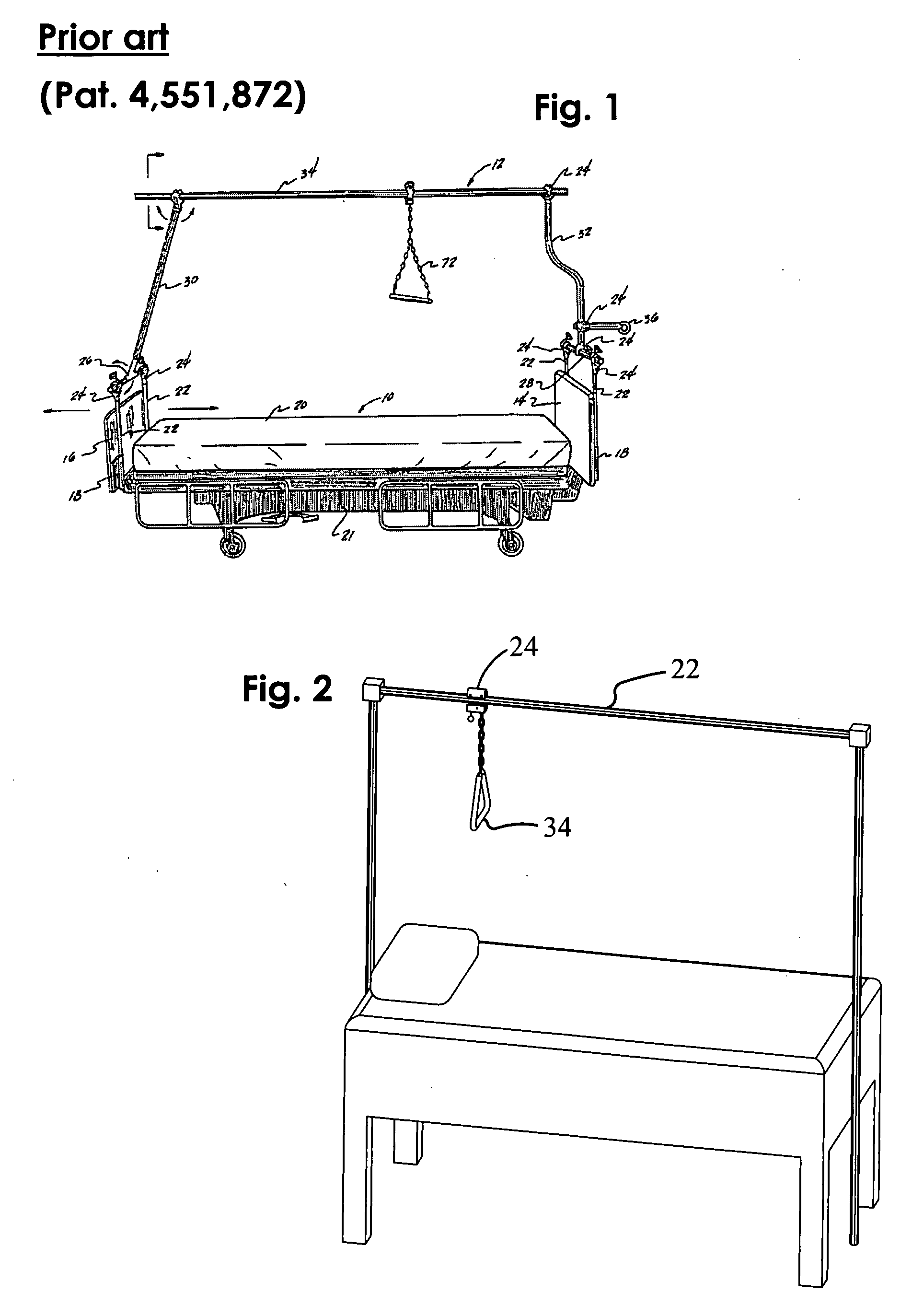
[0031]Referring initially to FIG. 1, a bed and a structural rail of the prior art are shown, and a clamp is shown at a typical position along the rail. Such a clamp is held at the spot selected for it, by virtue of manually tightening a bolt or screw around the rail. If a patient wishes to move himself with respect to the bed, he must either wiggle his body or get someone else to position the clamp in an advantageous location—so that he might benefit from being able to lift himself by pulling downwardly on a trapeze. Of course, the trapeze 20 is shown with a generally horizontal orientation, suspended below a rail 22 as it is typically employed in modern hospitals. Such a rail 22 is octagonal or circular in cross-section and has first and second ends and extends longitudinally over a hospital bed—as shown in U.S. Pat. No. 5,836,026 to Reed. The length of the rail 22 is not important to this invention, but there will be a variety of possible positions for a carriage 24 as it slides a...


PUM


Abstract

A support for a trapeze or other structure (such as a sling) that depends from a rail, said rail extending over a bed (usually a hospital bed) or other patient-support device. A carriage (which might also be called a trolley) is provided for selective movement—in small increments—along a conventional rail (having an octagonal or circular cross section) from one end to the other. Alternatively, the carriage is held static, where it provides a stable “anchor” for a trapeze, so that a person might safely pull downward on the trapeze. In one embodiment the static condition is initiated by the action of simply pulling downward on the trapeze, causing the carriage to bear against the rail with what may best be described as a “gripping” action. Switching between free movement along the rail and braked movement can be automatic, involving only a downwardly directed force on the carriage, which force may be supplied by an attending nurse or the patient.

Description

CROSS-REFERENCE TO A RELATED APPLICATION[0001]This C-I-P application contains subject matter that was present in an earlier application Ser. No. 11 / 357,838 dated Feb. 16, 2006, now abandoned.FIELD OF THE INVENTION[0002]This invention relates generally to the temporary lifting of a person with respect to a horizontal surface—such a bed on which the person may be reclining; more particularly, it relates to an improved manner of permitting a person to use his or her own strength to rise, temporarily, from a generally prone position to an alternate position.BACKGROUND OF THE INVENTION[0003]It is common for persons who are seriously ill or have been involved in a serious accident or the like to be restricted to a hospital bed for an extended period of time. Eventually, as they begin to recover from the effects of their illness or accident, they begin to feel restless and they want to change their position with respect to the supporting bed. In a typical hospital environment, when sliding...

Claims


Application Information

Patent Timeline
Patent Type & Authority Applications(United States)
IPC IPC(8): A61G7/10
CPCA61G7/0536A61G7/1042
Inventor PASTUSEK, JONATHAN EDWARD
Owner PASTUSEK JONATHAN EDWARD
Why Eureka
Try Eureka