Exercise machine having rotatable weight selection index
a weight selection index and exercise machine technology, applied in the field of exercise equipment, can solve the problems of wasting user energy, injury hazards, and relatively high friction generation, and achieve the effect of less smooth weight movement, less friction, and relatively high friction
- Summary
- Abstract
- Description
- Claims
- Application Information
AI Technical Summary
Benefits of technology
Problems solved by technology
Method used
Image
Examples
first embodiment
b. First Embodiment of the Weight Exercise Machine
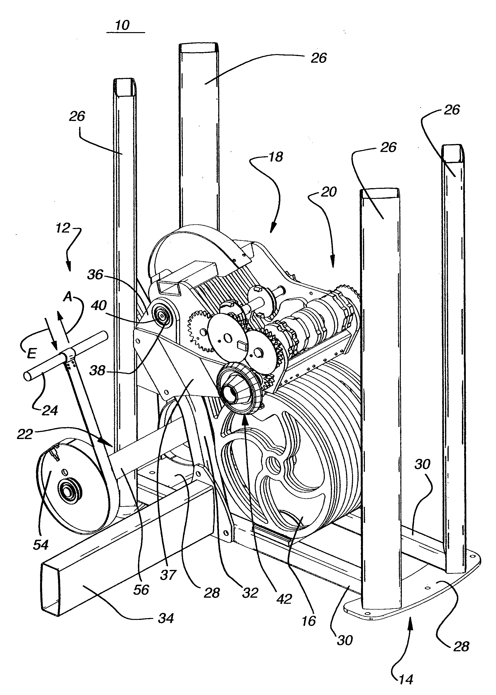
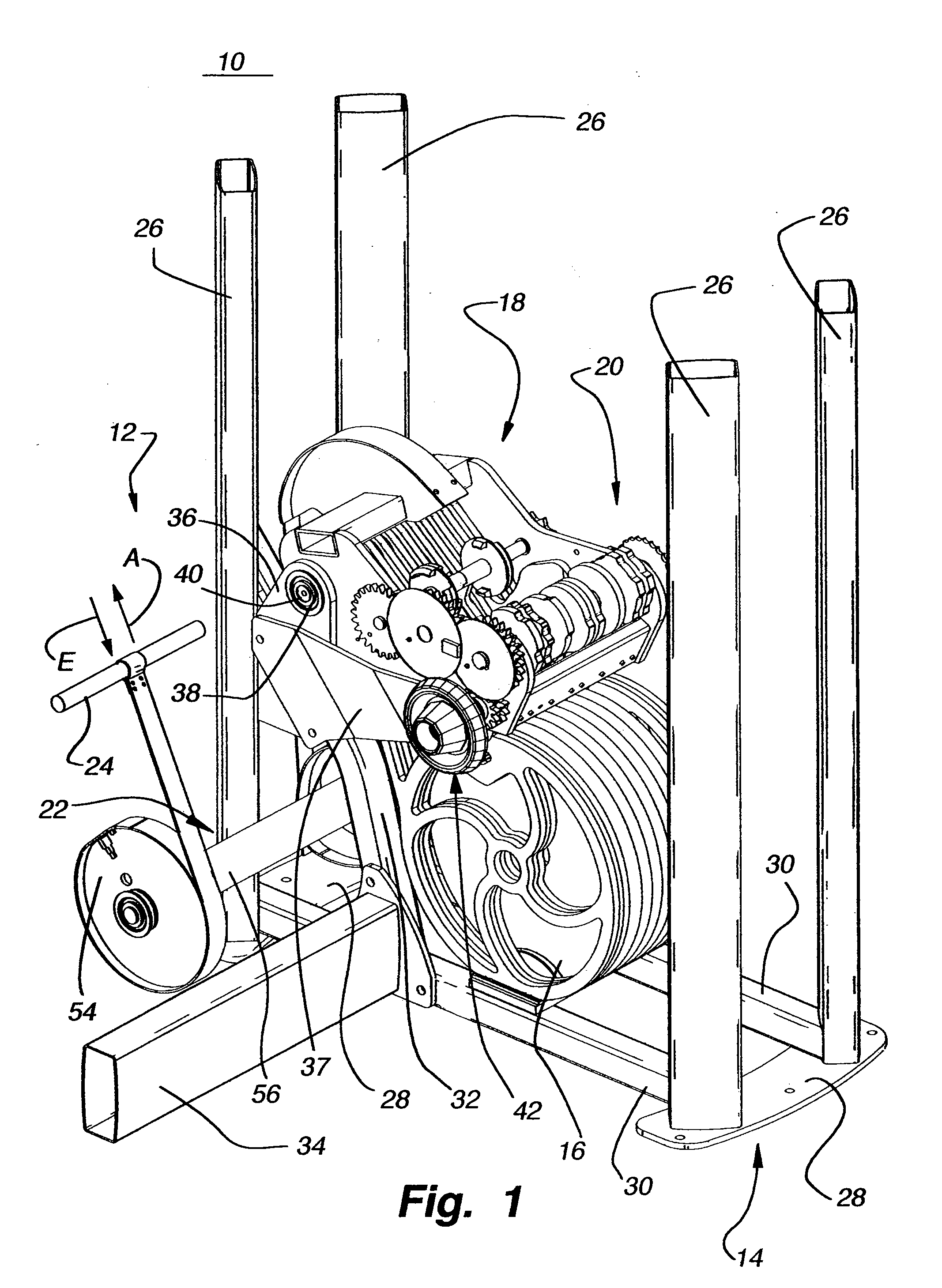
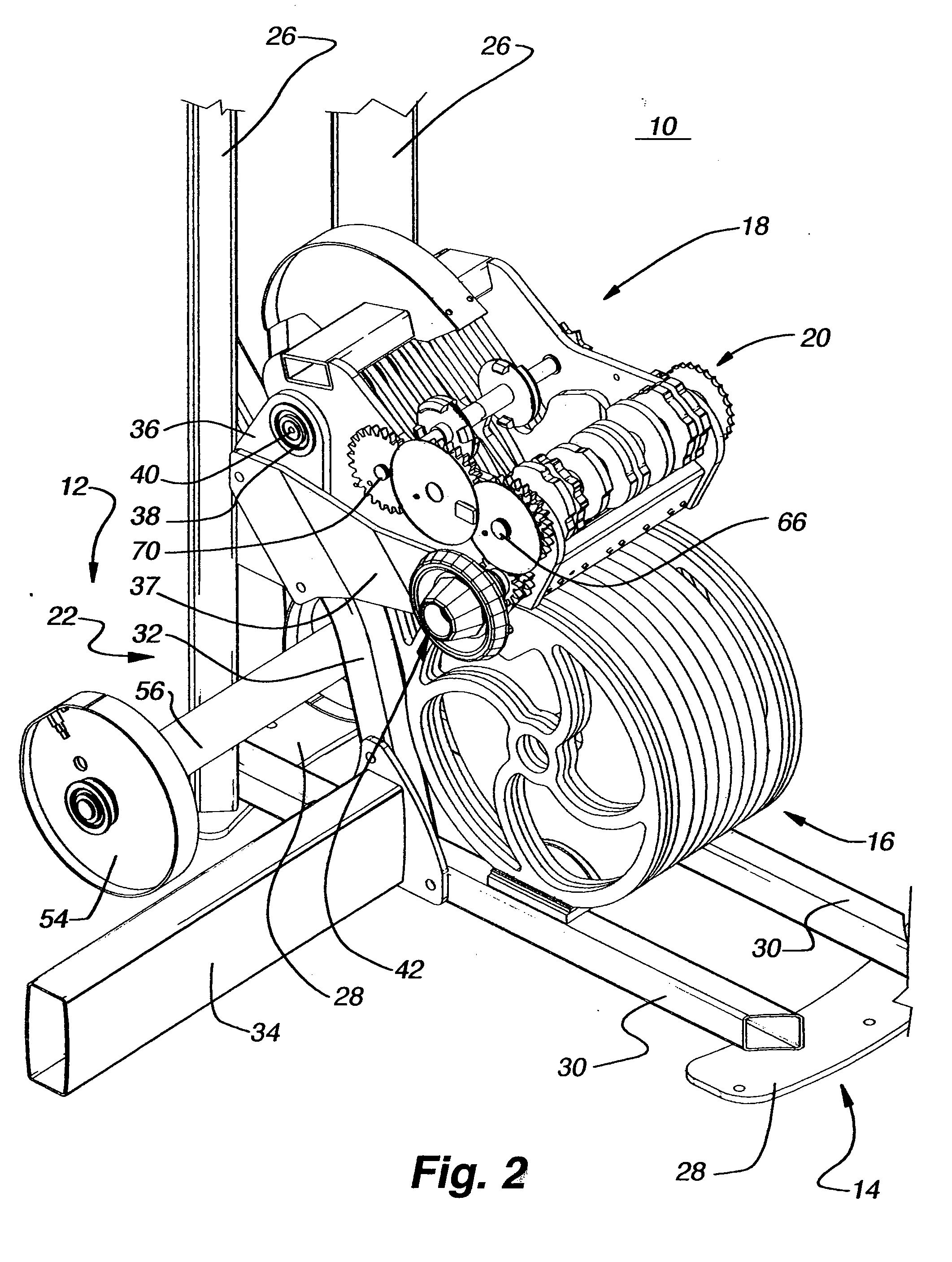
[0074]For an understanding of the overall configuration the first embodiment of the weight exercise machine 10 of the present invention and the relationships between the machine's various elements, reference is made to FIGS. 1-5. FIG. 1 is an isometric view of the weight exercise machine 10 as viewed from the front / user side of the machine 10. FIG. 2 is the same view depicted in FIG. 1, except, for clarity purposes, the view has been enlarged and the front vertical posts of the base frame have been removed. FIG. 3 is an isometric view of the exercise machine 10 as viewed from the front / non-user side of the machine 10, wherein the front vertical posts of the base frame have been removed for clarity purposes. FIG. 4 is an isometric view of the exercise machine 10 as viewed from the rear / user side of the machine 10, wherein the rear vertical posts of the base frame have been removed for clarity purposes. FIG. 5 is an isometric view of t...
second embodiment
c. Second Embodiment of the Weight Exercise Machine
[0106]For a discussion of the second embodiment of the weight exercise machine 310 of the present invention, reference is made to FIG. 22, which is a diagrammatical side elevation of the weight exercise machine 310. As shown in FIG. 22, the weight exercise machine 310 has a workstation 312, a base frame 314, weights 316, a weight arm assembly 318, a weight index mechanism 320, and a force transfer mechanism 322.
[0107]The workstation 312 includes an exercise member 324 and a user support platform 325 (e.g., a bench, seat, etc.) for supporting the user when utilizing the machine 310 to exercise. The user engages and displaces the exercise member 324 to exercise with the machine 310. For example, where the machine 310 is an embodiment intended to exercise portions of the upper body (e.g., shoulders, chest, back, arms, traps, etc.), the exercise member 324 will be configured for engagement by the user's hands and / or arms. Where the mach...
third embodiment
d. Third Embodiment of the Weight Exercise Machine
[0149]For a discussion of the third embodiment of the weight exercise machine of the present invention, reference is made to FIGS. 38-41. FIG. 38 is an isometric view of weights 516 and weight index mechanism 520 of the weight exercise machine. FIG. 39 is an isometric view of the index mechanism 520 wherein the weights 516 are not shown for clarity purposes. FIG. 40 is a front elevation of the weights 516 and weight indexing mechanism 520 wherein the indexing mechanism 520 is aligned with the selected / indexed weight 516a′ prior to displacement relative to the non-indexed / non-selected weights 516a″. FIG. 41 is the same view depicted in FIG. 40, except the index / selected weight 516a′ has been displaced relative from the non-indexed / non-selected weights 516a″ by a user displacing an exercise member.
[0150]As shown in FIG. 38, each weight 516a is a pie-slice segment 516a of a cylindrical mass having a center hole 522. As indicated in FIG....
PUM
 Abstract
Description
Claims
Application Information
 - R&D
- Intellectual Property
- Life Sciences
- Materials
- Tech Scout
- Unparalleled Data Quality
- Higher Quality Content
- 60% Fewer Hallucinations
Browse by: Latest US Patents, China's latest patents, Technical Efficacy Thesaurus, Application Domain, Technology Topic, Popular Technical Reports.
© 2025 PatSnap. All rights reserved.Legal|Privacy policy|Modern Slavery Act Transparency Statement|Sitemap|About US| Contact US: help@patsnap.com


