Pressure washer system and operating method

Active Publication Date: 2008-10-09
BLACK & DECKER INC
View PDF41 Cites 29 Cited by
  • Summary
  • Abstract
  • Description
  • Claims
  • Application Information

AI Technical Summary

Benefits of technology

[0004]Typically, the pump employed by pressure washers can be a piston pump having one or more reciprocating pistons for delivering liquid under pressure to an outlet or a device coupled to the outlet, such as a high-pressure spray wand. Such piston pumps often utilize two or more pistons to provide a generally more continuous spray, higher flow rate, and greater efficiency. Multiple piston pumps can employ articulated pistons (utilizing a journal bearing and wrist pins) or may utilize a swash plate and linear pistons for pumping the liquid. Generally, when the pump is activated by the power source, the pump remains active for the duration of the use of the pressure washer. This can result in increased wear on the pump, and thus can wear a motor coupled to the pump. Accordingly, it would be desirable to provide a pressure washer that includes a clutch to engage and disengage the pump during the operation of the pressure washer.

Problems solved by technology

This can result in increased wear on the pump, and thus can wear a motor coupled to the pump.

Method used


Image

  • Pressure washer system and operating method
  • Pressure washer system and operating method
  • Pressure washer system and operating method

Examples


Embodiment Construction

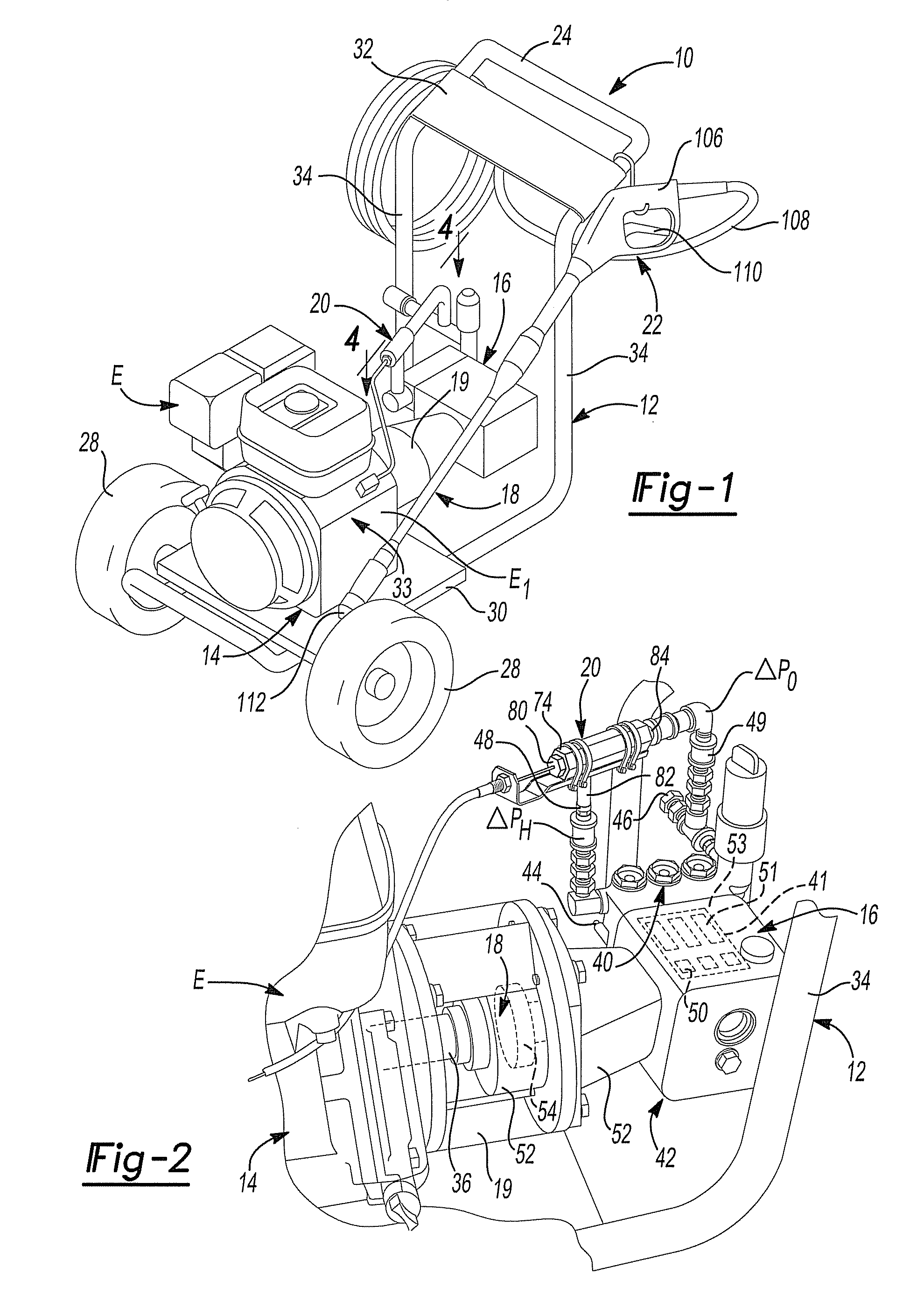
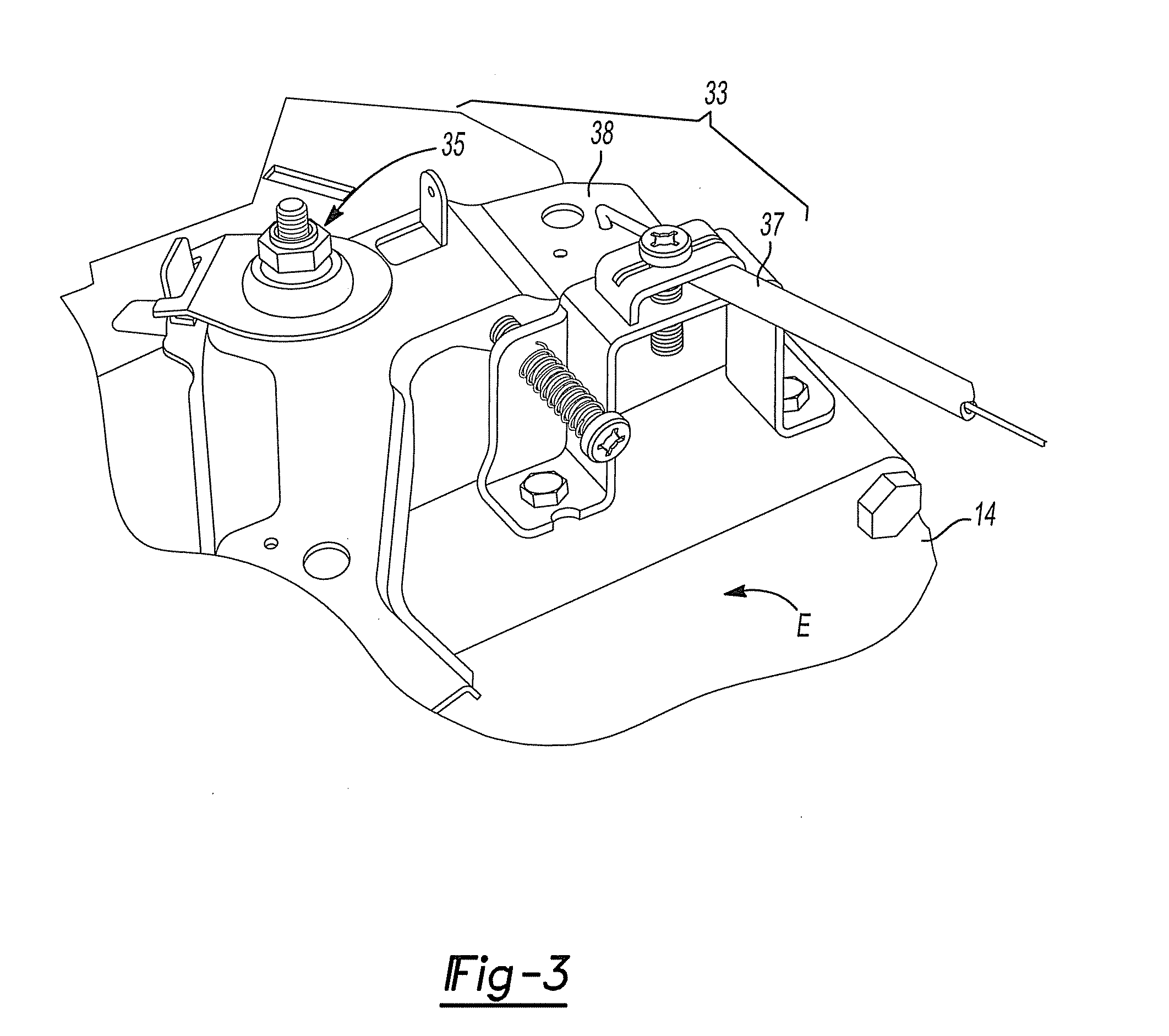
[0014]With reference to FIGS. 1 and 2 of the drawings, an exemplary pressure washer constructed in accordance with the teachings of the present disclosure is generally indicated by reference numeral 10. The pressure washer 10 can include a frame 12, a power source 14, a pump assembly 16, a clutch 18, a guard or support 19, which is disposed about the clutch 18 and coupled to the power source 14 and the pump assembly 16, an actuator system 20 and a sprayer system 22 for delivering the high pressure fluid.

[0015]The frame 12 can be constructed in any convenient manner to support the power source 14, such as that which is described in U.S. Pat. No. 7,125,228, entitled “Pressure Washer Having Oilless High Pressure Pump”, the disclosure of which is incorporated by reference as if set forth in its entirety herein. Accordingly, the frame 12 need not be discussed in significant detail herein. Briefly, the frame 12 can include a handle 24, one or more wheels 28, and a body 30. The handle 24 c...


PUM


Abstract

A pressure washer is provided. The pressure washer can include a frame and a power source coupled to the frame. The power source can include an output shaft. The pressure washer can include a centrifugal clutch. The centrifugal clutch can include an input portion operably coupled to the output shaft and an output portion. The input portion of the centrifugal clutch can be operable to be selectively coupled to the output portion. The pressure washer can include a pump assembly, which can include a pump mechanism operably coupled with the output portion of the centrifugal clutch to pressurize a fluid when the input portion of the centrifugal clutch is coupled to the output portion. The pressure washer can also include an actuator in communication with at least the power source to actuate the power source to drive the output shaft.

Description

CROSS-REFERENCE TO RELATED APPLICATION[0001]This application takes priority from U.S. Patent Application Ser. No. 60 / 910,145 filed Apr. 4, 2007. The disclosure of the above application is incorporated herein by reference.INTRODUCTION[0002]The present disclosure generally relates to pressure washers. More particularly, the present disclosure relates to a pressure washer having a clutch disposed between a power source and a high pressure pump and a related method for operating a pressure washer.[0003]Generally, high pressure washing systems, commonly referred to as pressure washers, can operate to deliver a high pressure fluid, such as water, to a desired surface. The high pressure fluid can be used to clean, strip or prepare the surface for other treatment. Pressure washers can be produced in a variety of designs and can be used to perform numerous functions in industrial, commercial and home applications. Pressure washers can be stationary or portable. Generally, stationary pressure...

Claims


Application Information

Patent Timeline
IPC IPC(8): B05B9/01F04B17/05F04B49/02B05B9/04F04B49/08
CPCF04B17/05
Inventor PARRIS, GREGORY L.RICE, DANIEL W.JENKINS, JOSEPH L.
Owner BLACK & DECKER INC
Why Eureka
Try Eureka