
Managing Power Allocation To Ethernet Ports In The Absence Of Mutually Exclusive Detection And Powering Cycles In Hardware

a technology of ethernet ports and power allocation, applied in the field of power over ethernet (poe) systems, can solve the problems of not including such hardware support, power cannot be pre-allocated in these ethernet switches in the manner described, and it is not possible to enable some ports, so as to prevent power allocation problems

Active Publication Date: 2008-10-02
ARRIS ENTERPRISES LLC
View PDF55 Cites 62 Cited by
  • Summary
  • Abstract
  • Description
  • Claims
  • Application Information

AI Technical Summary

Benefits of technology

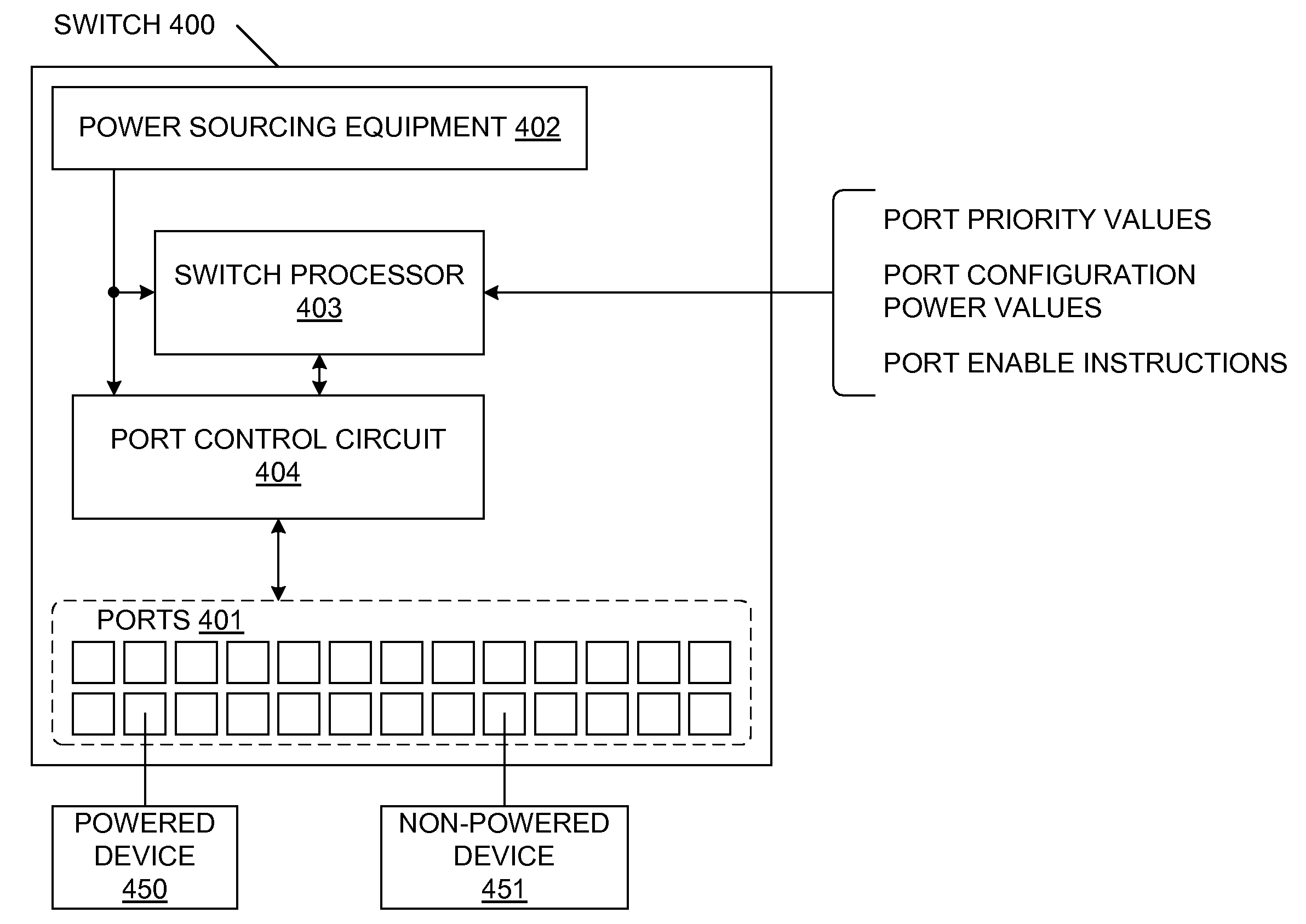
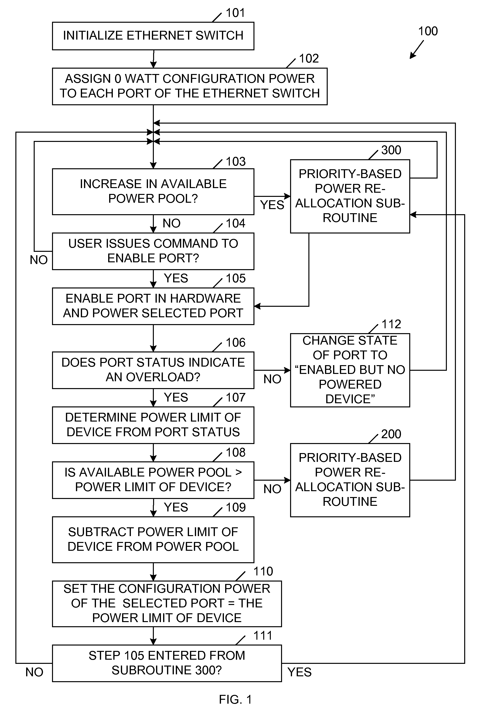
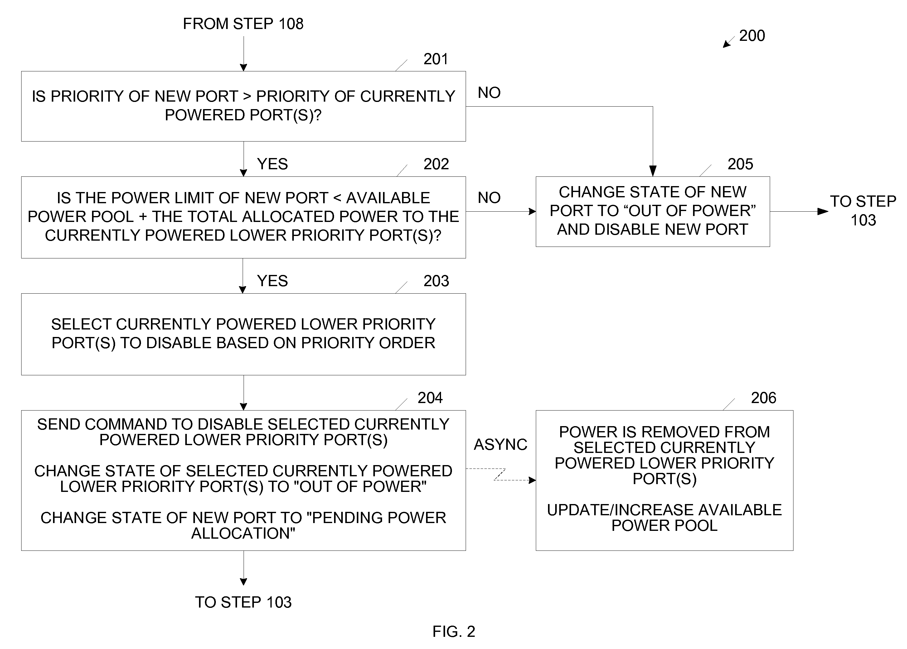
The present invention provides an improved method for pre-allocating power to the ports of an Ethernet switch. The invention includes hardware and software that detects the presence of a powered device on a port and assigns a priority to each port. The system software determines the available capacity of the power sourcing equipment and assigns a configuration power of 0 Watts to each port. The system software then enables each port in a step-wise manner, starting with the port with the highest priority. If there is an overload condition, the system software redefines the configuration power of the port based on the power limit of the connected device. The invention prevents power allocation problems and ensures efficient power allocation.

Problems solved by technology

However, some Ethernet switches do not include such hardware support.
Thus, power cannot be pre-allocated in these Ethernet switches in the manner described above.
As a result, it may not be possible to enable some ports (even though actual power capacity exists to supply these ports).
The software may never address the power needs of these ports.
This problem becomes worse in Ethernet switches having a large number of ports (i.e., 192 ports).
Note that typical power supply equipment used in an Ethernet switch is not capable of powering 192 ports at the maximum rated power of 15.4 Watts per port.
Failure to pre-allocate power will cause the Ethernet switches of the second type to fail to meet the specifications of the IEEE 802.3af standard.

Method used


Image

  • Managing Power Allocation To Ethernet Ports In The Absence Of Mutually Exclusive Detection And Powering Cycles In Hardware
  • Managing Power Allocation To Ethernet Ports In The Absence Of Mutually Exclusive Detection And Powering Cycles In Hardware
  • Managing Power Allocation To Ethernet Ports In The Absence Of Mutually Exclusive Detection And Powering Cycles In Hardware

Examples


Embodiment Construction

[0023]The present invention provides an improved method for pre-allocating power in a system that uses an Ethernet switch that detects the presence of a powered device and enables power to the powered device in a single, indivisible operation.

[0024]FIG. 1 is a flow diagram 100 illustrating a method in accordance with one embodiment of the present invention. The Ethernet switch is initialized in Step 101. In general, this initialization step resets the Ethernet switch, determines the amount of power available to supply powered devices (i.e., determines the capacity of the power sourcing equipment, or the size or the ‘power pool’), and sets the priority of the various ports of the Ethernet switch. For example, the initial available capacity of the power pool may be 1080 Watts (at 48 Volts).

[0025]In Step 102, which may be considered part of the initialization of the Ethernet switch, the system software assigns a configuration power of 0 Watts to each port of the Ethernet switch. The co...


PUM


Abstract

A method of allocating power to ports in an Ethernet switch, including: (1) assigning a configuration power to a selected port, wherein the assigned configuration power is less than a power supplied by the selected port to a powered, (2) enabling and powering the selected port in a single indivisible step, (3) determining the power limit of a device coupled to the selected port, (4) comparing the power supplied by the selected port to the device with the configuration power assigned to the selected port, and (5) if the power supplied by the selected port to the device is greater than the configuration power assigned to the selected port, then increasing the configuration power of the selected port to correspond with the power limit of the device.

Description

FIELD OF THE INVENTION[0001]The present invention relates to a power over Ethernet (PoE) system. More specifically, embodiments of the present invention relate to an improved method for pre-allocating power to ports in a PoE system that simultaneously enables and powers the ports in a single, indivisible step.RELATED ART[0002]In a power over Ethernet (PoE) system, one or more Ethernet devices connected to an Ethernet network are powered over the network cables. Power sourcing equipment located in an Ethernet switch is used to supply the power on the network cables. Ethernet devices which are configured to operate in response to the power supplied on the network cables are commonly referred to as powered Ethernet devices, or simply powered devices (PDs). As defined herein, Ethernet devices which are configured to receive power from a separate power supply (e.g., a conventional 120 Volt AC outlet) will be referred to as non-system powered Ethernet devices.[0003]The power sourcing equi...

Claims


Application Information

Patent Timeline
Patent Type & Authority Applications(United States)
IPC IPC(8): G06F1/26
CPCG06F1/266H04L12/10
Inventor HANSALIA, RAKESHBALASUBRAMANIAN, ADOOR V.
Owner ARRIS ENTERPRISES LLC
Learn More