Servo pattern recording device

a technology of servo pattern and recording device, which is applied in the field of servo pattern recording device, can solve the problems of difficult to improve recording accuracy and transmission of motor vibration, and achieve the effects of reducing transmission of vibration, preventing the degraded and improving the recording accuracy of servo pattern

Inactive Publication Date: 2008-10-02
TDK CORPARATION
View PDF9 Cites 0 Cited by
  • Summary
  • Abstract
  • Description
  • Claims
  • Application Information

AI Technical Summary

Benefits of technology

[0006]The present invention was made in view of these problems, and a main object of the present invention is to provide a servo pattern recording device which is capable of improving recording accuracy of a servo pattern.
[0014]Further, it is possible to connect the second sub panel to the main panel with a vibration isolator interposed between the second sub panel and the main panel. With this configuration, it is possible to more reliably reduce transmission of vibration caused by the capstan motor to the magnetic head, thereby making it possible further improve the recording accuracy of the servo pattern.

Problems solved by technology

In the conventional servo writer, however, since the motors are fixed on the panel side together with the servo signal write head as described above, there is a risk of the vibrations of the motors being transmitted to the servo signal write head, which makes it difficult to improve recording accuracy.

Method used


Image

  • Servo pattern recording device
  • Servo pattern recording device
  • Servo pattern recording device

Examples


Embodiment Construction

[0027]Hereinafter, the best mode of a servo pattern recording device according to the present invention will be described with reference to the accompanying drawings.

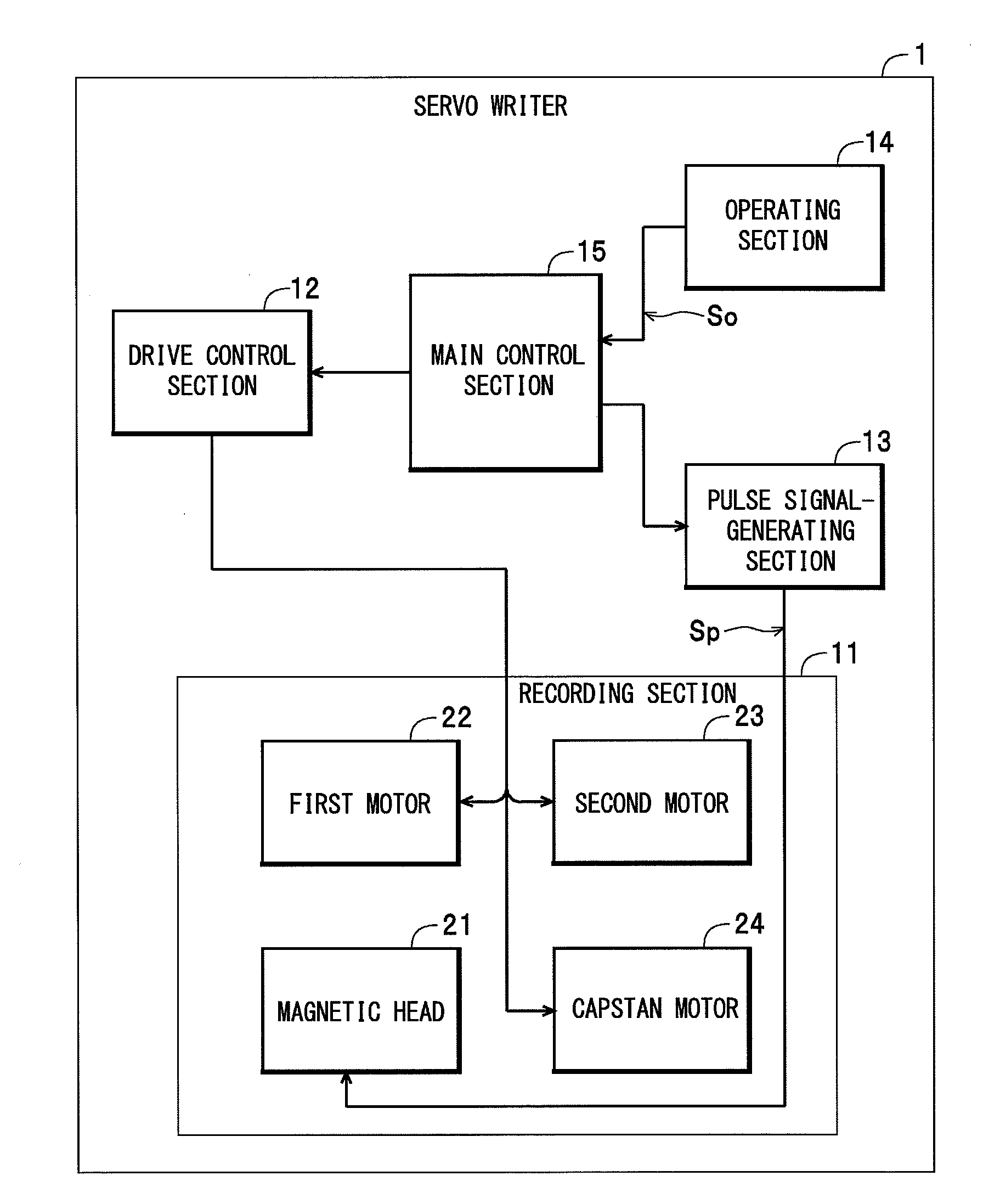
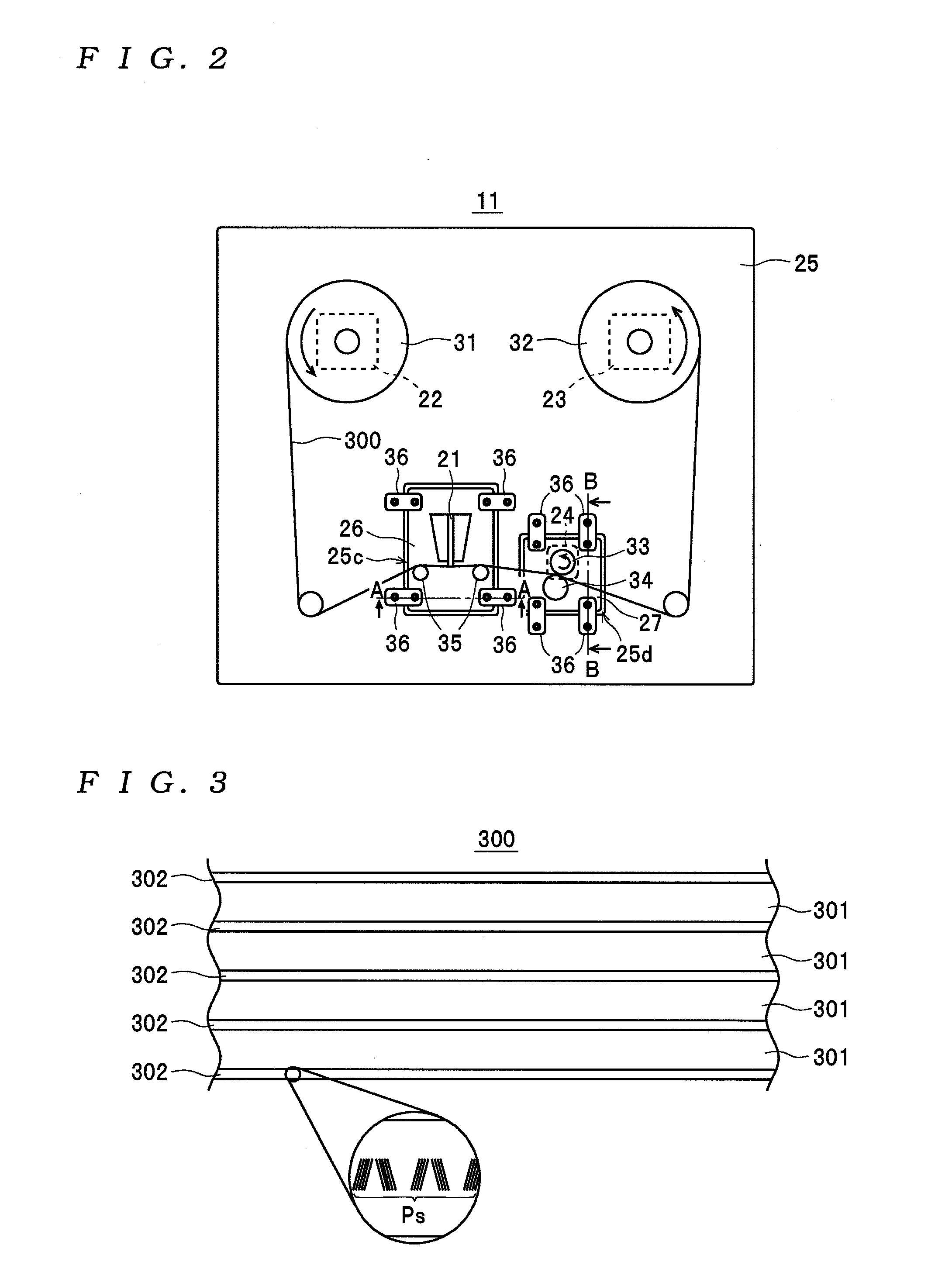
[0028]First, a description will be given of the construction of a servo writer 1. The servo writer 1 shown in FIG. 1 is an example of the servo pattern recording device according to the present invention. The servo writer 1 is comprised of a recording section 11, a drive control section 12, a pulse signal-generating section 13, an operating section 14, and a main control section 15, and is configured such that it can record a servo pattern Ps appearing in FIG. 3, on a magnetic tape 300 shown in FIG. 3. Here, the servo pattern Ps is for use in tracking servo used for controlling the tracking of a recording and reproducing head of a recording and reproducing device, not shown, which records data on the magnetic tape 300 and reproduces the recorded data. As shown in FIG. 3, the servo pattern Ps is recorded e.g., in a total...


PUM

PropertyMeasurementUnit
tape speedsaaaaaaaaaa

Abstract

A servo pattern recording device capable of improving the recording accuracy of a servo pattern. The servo pattern recording device is comprised of a magnetic head that records a servo pattern for tracking servo on a magnetic tape, a first motor that feeds the magnetic tape, a second motor that takes up the magnetic tape, and a main panel along a surface of which the magnetic tape is caused to move. The first motor and the second motor are mounted on the main panel, and the magnetic head is mounted on a first sub panel that is formed separately from the main panel and is connected to the main panel via a connecting member.

Description

BACKGROUND OF THE INVENTION[0001]1. Field of the Invention[0002]The present invention relates to a servo pattern recording device that records a servo pattern for tracking servo on a magnetic tape.[0003]2. Description of the Related Art[0004]As a servo pattern recording device of this kind, there is known a servo writer disclosed in Japanese Laid-Open Patent Publication (Kokai) No. 2005-92938. This servo writer is comprised of a feed reel for feeding a magnetic tape, a take-up reel for taking up the magnetic tape, a servo signal write head for writing a servo signal (servo pattern) for tracking servo on the magnetic tape, and so forth. In this case, the servo signal write head is removably mounted on a head base member fixed on a panel side (panel). This makes it possible to replace the servo signal write head relatively easily.SUMMARY OF THE INVENTION[0005]From the study of the above-described servo writer, the present inventors found out the following problems. In general, a servo...

Claims


Application Information

Patent Timeline
Patent Type & Authority Applications(United States)
IPC IPC(8): G11B5/33
CPCG11B5/584
Inventor INOUE, OSAMUTESHIMA, KEIJIMATSUNO, KOJIHANDA, TAKASHIFUJITA, KAZUTAKA
Owner TDK CORPARATION
Why Eureka
Try Eureka