
System and method for demand dispatch and load management

a demand dispatching and load management technology, applied in the field of system and method for demand dispatching and load management, can solve the problems of environmental impact, other costs of acquiring additional capacity, and the cost of acquiring capacity to meet peak demand, so as to reduce operational risks, reduce the utilization of resources, and increase the aggregate utilization level. the effect of efficiency

Inactive Publication Date: 2008-10-02
BPL GLOBAL
View PDF11 Cites 124 Cited by
  • Summary
  • Abstract
  • Description
  • Claims
  • Application Information

AI Technical Summary

Benefits of technology

[0013]Exemplary embodiments of the system and method may provide many benefits while meeting the utilization demands. These benefits include reducing operational risks. In the electricity distribution industry, the operational risks that can be reduced include risk of rolling blackouts, profit risk due to volatility of energy feedstock, risk to assets from overload conditions, risks to customers from outages, and risk to the environment from CO2 and other emissions.

Problems solved by technology

In the case of electricity distribution, cost of acquiring capacity to meet peak demand, such as building new power plants, can be enormous.
Also, acquiring additional capacity has other costs such as environmental impacts due to increased emission of pollutants.
Further, significant regulatory hurdles exist that delay the implementation of new power plants.
However, wholesale costs of electricity are highest during peak demand.
These costs may not be passed on to the consumers or may be only partially passed on for various reasons, which erodes the profitability of utilities.
Also, when a utility elects to purchase peak energy to meet growing demand, the increased demand can exceed the design parameters of transmission / distribution substations and circuits.
Some or all of these upgrades may require regulatory approval, and / or encounter lengthy delays.
Further, the assets of the utilities (e.g., distribution lines, transformers, feeders, and underground cables) deteriorate more quickly if they are operated over some specified tolerance limits.
For example, overstressed transformers may quickly blow and cease to operate, which disrupts power to many customers.
In addition, costs associated with repairing equipment can be significant.

Method used


Image

  • System and method for demand dispatch and load management
  • System and method for demand dispatch and load management
  • System and method for demand dispatch and load management

Examples


Embodiment Construction

[0018]For simplicity and illustrative purposes, the principles of the invention are described by referring mainly to exemplary embodiments thereof. However, one of ordinary skill in the art would readily recognize that the same principles are equally applicable to many types of demand dispatching and load management.

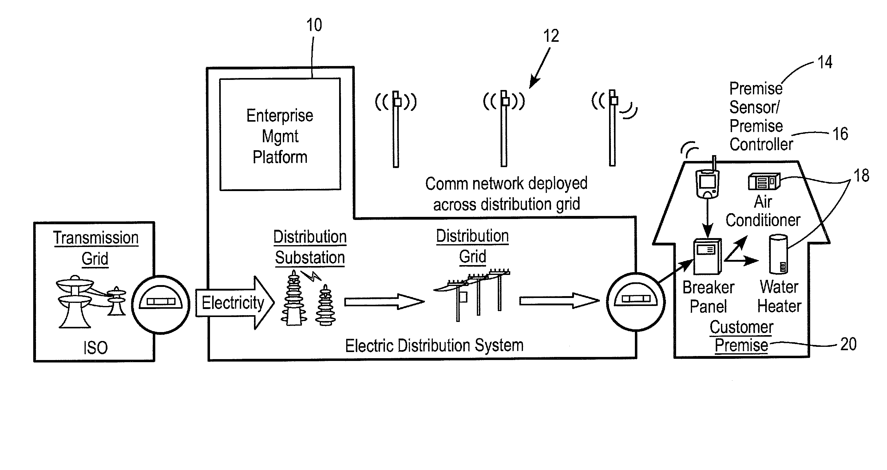
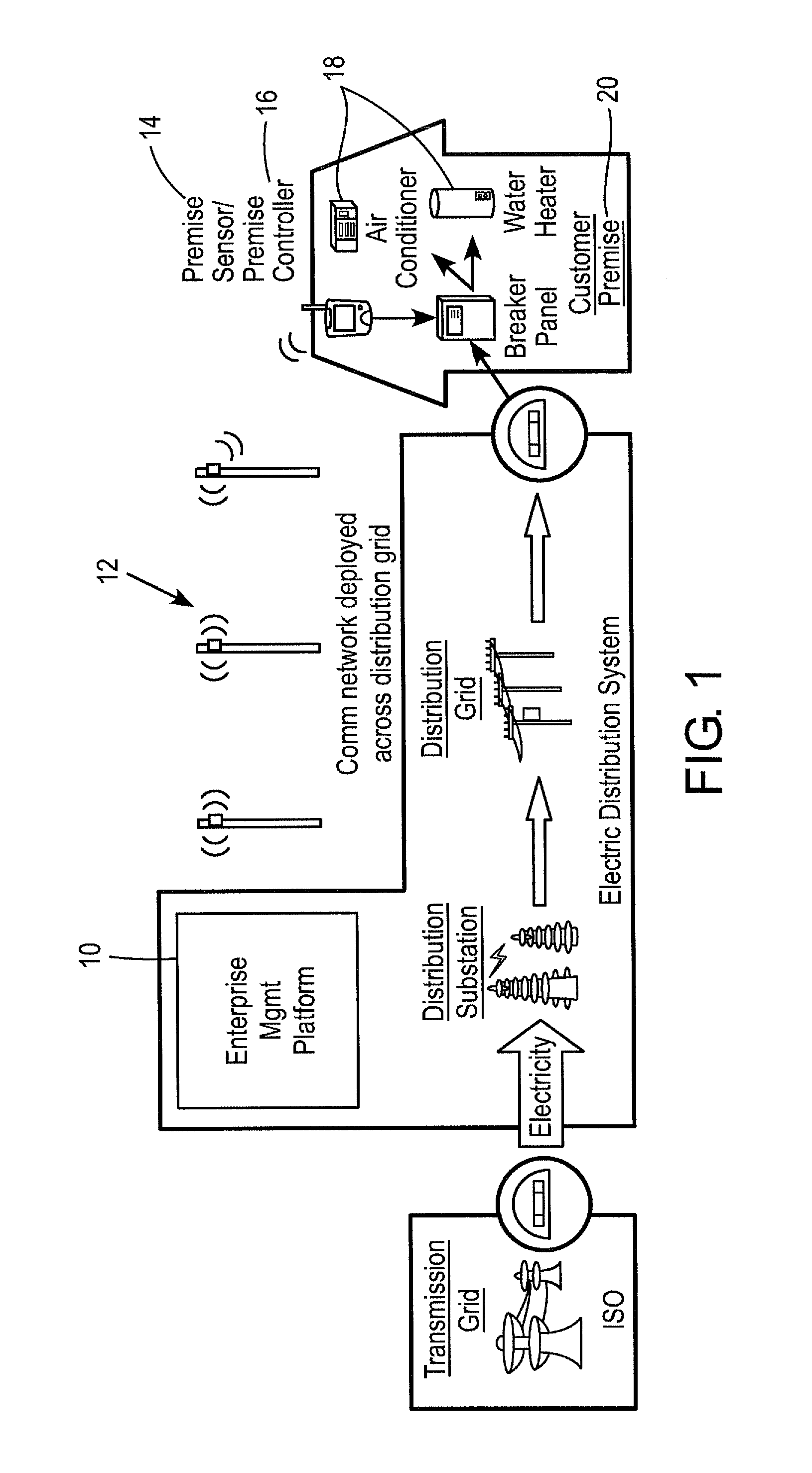
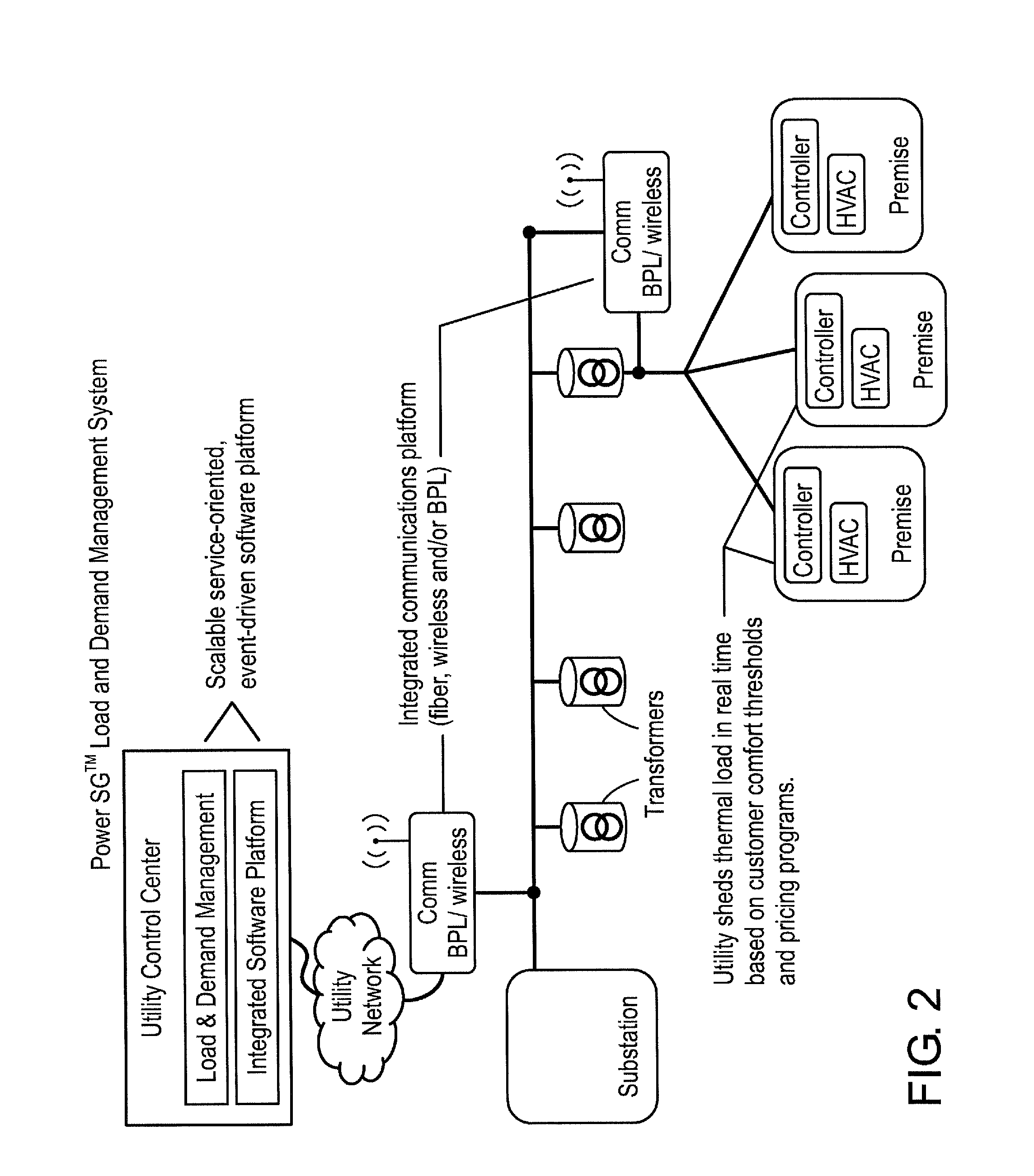
[0019]An embodiment of the invention involves a software program and hardware control system that can govern the aggregated utilization of a resource in a distribution service area. The controlled service area can be as broad as a utility's entire distribution network or as specific as individual customer premises. The software program may use configurable rules to manage individual utilization of the resource at the customer premise via a circuit controller and a communications network. Information regarding the individual utilization of the resource is fed back to the system (e.g., a central database) through the communications network. The software program can use alg...


PUM


Abstract

Provided is a system and method for monitoring utilization of a resource across an entire distribution area. The system dynamically and intelligently limits the aggregated utilization of the resource across an entire distribution area or targeted sub areas. Targeted usage thresholds at the device (individual utilization) level, as well as utility-specified business and technical rules and overrides, can be applied. Using these rules, the system continuously looks for and manages individual utilization of the resource that is available for curtailment, thus producing a larger and more efficient utilization level that is available for reduction without service impact to customers within that service area or targeted sub areas.

Description

PRIORITY STATEMENT[0001]This disclosure claims the benefit of prior Provisional Application No. 60 / 907,185 filed on Mar. 23, 2007, which is hereby incorporated by reference in its entirety.FIELD[0002]This invention relates generally to systems and methods of governing an aggregated utilization of a resource and to manage the supply and demand of the resource.BACKGROUND OF THE INVENTION[0003]Management of generation and distribution of a resource is highly desirable. This is especially true in the distribution of utility resources such as electricity, gas, and water. In the case of electricity distribution, cost of acquiring capacity to meet peak demand, such as building new power plants, can be enormous. This cost is usually passed on to the customers in the form of higher electric bills. Also, acquiring additional capacity has other costs such as environmental impacts due to increased emission of pollutants. Further, significant regulatory hurdles exist that delay the implementatio...

Claims


Application Information

Patent Timeline
IPC IPC(8): G08C19/16
CPCG06Q10/06G06Q50/06
Inventor TOLNAR, JEFFCAROLINE, HEIDIHYMER, LARRYBAUER, MICHAEL
Owner BPL GLOBAL
Learn More