
Device for stowing a road vehicle on a bearing plane so that it can be transported by another vehicle

a technology for securing a road vehicle and a bearing plane, which is applied in the direction of vehicle carriers, transportation items, items transportation vehicles, etc., can solve the problems of less attention and precision in the actions of operators, the inability of chain or cable systems and the inability to adapt to wheels or tires

Inactive Publication Date: 2008-09-25
LOHR IND
View PDF6 Cites 21 Cited by
  • Summary
  • Abstract
  • Description
  • Claims
  • Application Information

AI Technical Summary

Benefits of technology

[0021]This invention aims to eliminate these disadvantages and to add other advantages by proposing a dual-purpose securing device using a strap making it possible to secure a vehicle on a bearing plane for each strap via one of its wheels and from at least one anchoring point on the chassis.
[0026]A mobile coupling and transmission assembly formed of two separable parts that slot together or fit into each other, making it possible to secure the vehicle being transported at a point of its chassis.

Problems solved by technology

This necessity stems from the often sudden jolts of certain amplitude experienced by the chassis of the truck or the freight car while moving and to flaws in the roads or railroad tracks.
On the one hand, chains and even cables constitute additional weight to be transported and used; on the other hand, their weight and the necessity of compressing the suspensions requires considerable effort which results in fatigue and, as a result, in risks for the operators, as well as less attention to and less precision in their actions.
From both an economical and work safety standpoint, these disadvantages lead to a need for a device for securing to the chassis that is light, effective and easy to use.
Furthermore, chain or cable systems cannot be adapted to wheels or tires due to the damage that may cause.

Method used


Image

  • Device for stowing a road vehicle on a bearing plane so that it can be transported by another vehicle
  • Device for stowing a road vehicle on a bearing plane so that it can be transported by another vehicle
  • Device for stowing a road vehicle on a bearing plane so that it can be transported by another vehicle

Examples


Embodiment Construction

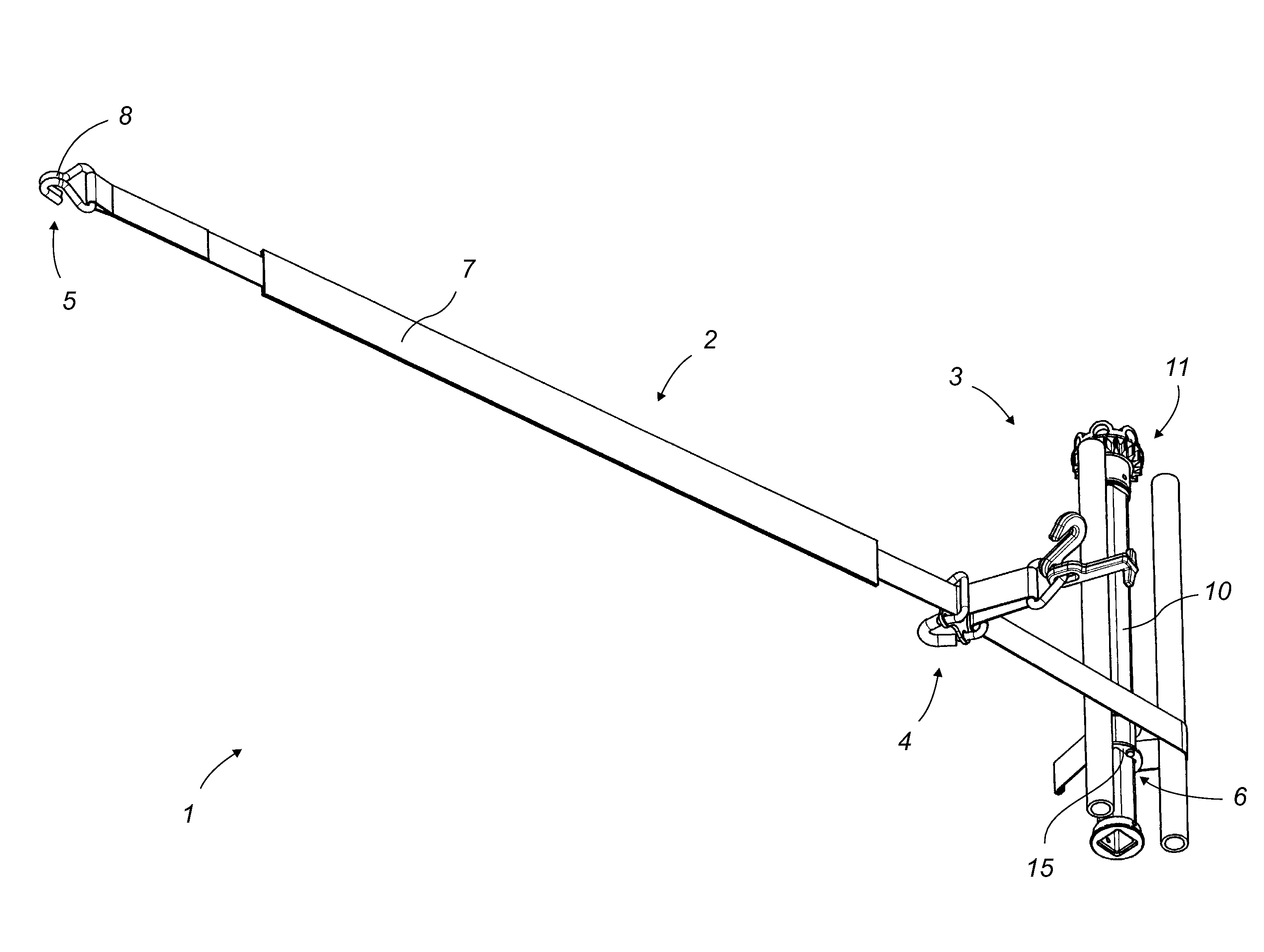
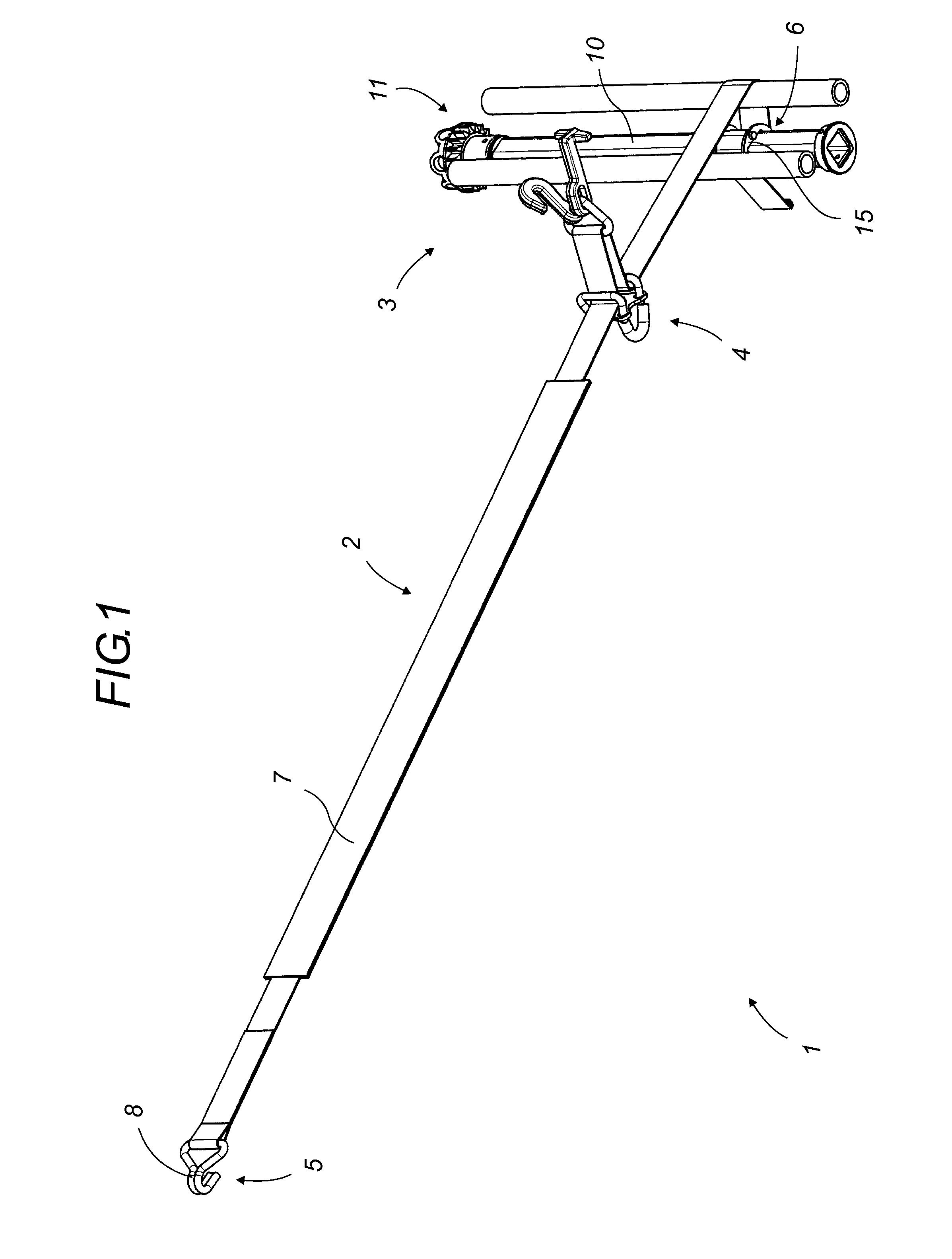
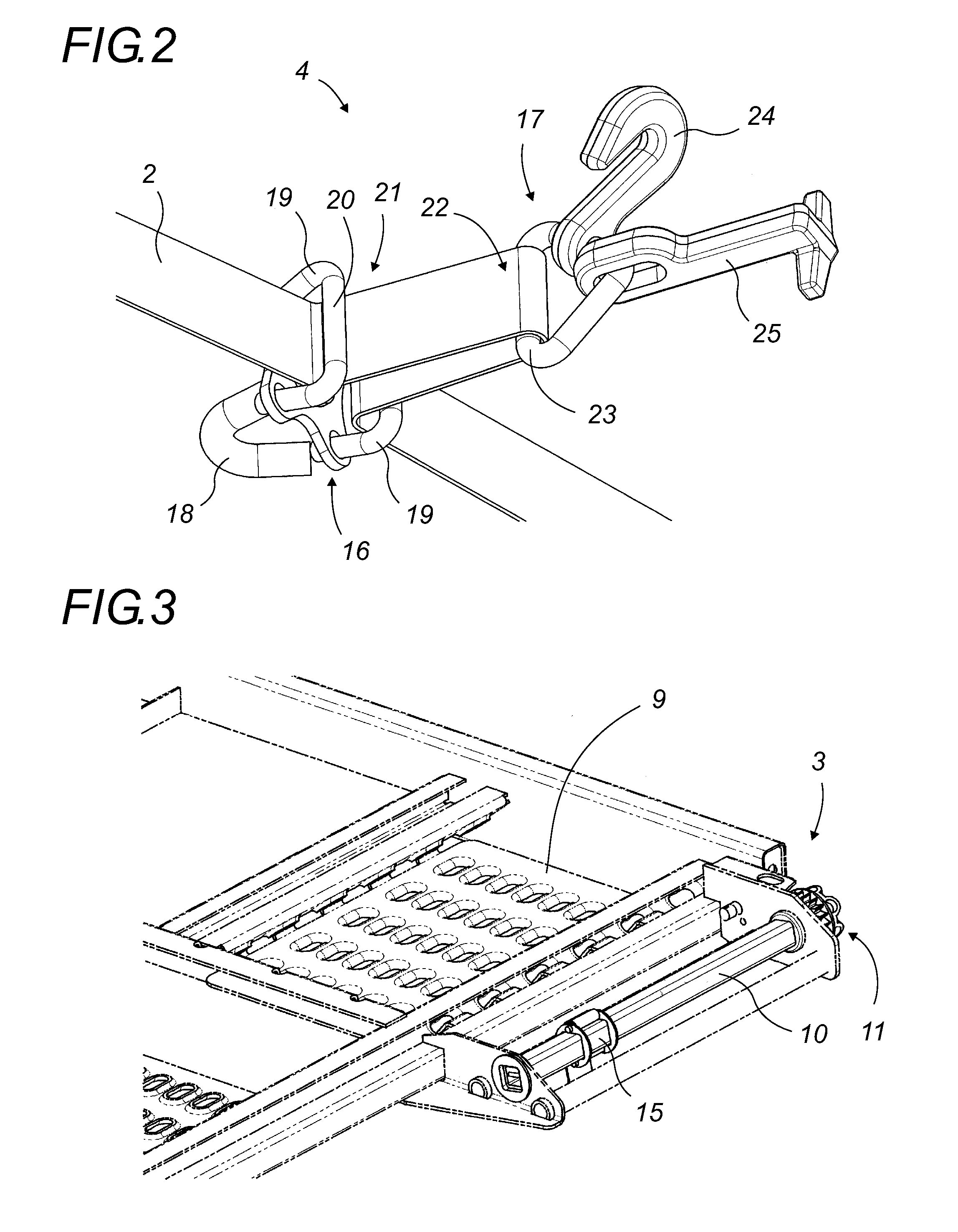
[0038]The securing device according to this invention will now be described in detail by referring to FIGS. 1 through 10. Equivalent items shown in the different figures will have the same numerical references.

[0039]The securing device 1, as shown in its entirety in FIG. 1, generally consists of a link and more specifically a strap 2 or analogous component, a tensioning and retaining mechanism 3 for the link and a coupling and transmission assembly 4 passed through by the link.

[0040]Hereinafter we will use the term “strap,” since it is more general and covers all suitable types of links.

[0041]The strap 2 or analogous component has a coupling end 5 and another end, for example a tensioning end 6 provided to engage with the tensioning and retaining mechanism 3 of the strap 2. This strap or analogous component also has one or more means of contact against the tire, for example in the form of a sliding sheath 7 or several transversal support bars.

[0042]Its coupling end 5 preferably comp...


PUM


Abstract

The device (1) for stowing a vehicle when it is transported on a bearing plane (9) by one of its wheels or from an anchorage on the chassis is characterized in that it is constituted by the following means: a link (2) that has a coupling end (5) provided to engage with a tensioning and retaining mechanism (3), a tensioning end (6), and a sliding sheath (7) for support on a tyre, a mechanism for tensioning and retaining the link (2) that has a roll axis (10) of sufficient length to offer numerous transverse coiling positions of the strap, and a coupling and return assembly (4) passed through by the link (2). Said device therefore enables vehicles to be stowed in two ways: a) by coupling to the vehicle chassis and b) by stowing the vehicle by link (2) on its tyres. This invention relates to the transportation of vehicles on Lorries or railway trucks.

Description

[0001]This application is a continuation of International Application PCT / FR2007 / 000617 which was filed Apr. 12, 2007, which in turn claims priority from French patent application serial no. 0603277 filed Apr. 13, 2006.FIELD OF THE INVENTION[0002]The invention relates to a device for securing a road vehicle on another vehicle so that it can be transported on a bearing plane of this other vehicle.BACKGROUND OF THE INVENTION[0003]The invention comes within the domain of securing road vehicles as loads on loading planes of trucks or freight cars.[0004]When transporting cars and, more generally, road vehicles on trucks or freight cars specifically for this use, the vehicles transported are secured on bearing planes to guarantee that they do not move during travel.[0005]This necessity stems from the often sudden jolts of certain amplitude experienced by the chassis of the truck or the freight car while moving and to flaws in the roads or railroad tracks.[0006]There are currently two main...

Claims


Application Information

Patent Timeline
Patent Type & Authority Applications(United States)
IPC IPC(8): B60P3/06
CPCB60P3/079B60P3/075
Inventor BLANCHET, BERTRAND
Owner LOHR IND
Learn More