Sheet conveying device and image forming apparatus

Inactive Publication Date: 2008-09-25
RICOH KK
View PDF6 Cites 61 Cited by
  • Summary
  • Abstract
  • Description
  • Claims
  • Application Information

AI Technical Summary

Benefits of technology

[0013]It is an object of the present invention to at least

Problems solved by technology

However, when a sheet with a certain level of thickness enters into a secondary transfer unit, the speed of the intermediate transfer member being driven at a certain speed drops for a short period of time.
This disturbs image forming operation in the primary transfer unit.
This disturbs image forming operation in the secondary transfer unit as in the intermediate transfer unit.
In this case also, when a sheet with a certain level of thickness enters into a transfer-fixing unit, the speed of the intermediate transfer member being driven at a certain speed drops for a short period of time, thereby causing a problem that the image is disturbed in the primary and secondary transfer units, as at the time of entering into the secondary transfer unit.
Moreover, because a control target value preset based on the type, thickness and width of a sheet is used, it is difficult to perform optimum control with respect to all usable sheets.
Furthermore, even with the same sheet, the thickness and firmness change according to environmental conditions such as temperature and humidity, and fluctuation of speed caused thereby is different, and therefore, optimum control is difficult to perform.

Method used


Image

  • Sheet conveying device and image forming apparatus
  • Sheet conveying device and image forming apparatus
  • Sheet conveying device and image forming apparatus

Examples


Embodiment Construction

[0032]Exemplary embodiments of the present invention are explained in detail below with reference to the accompanying drawings.

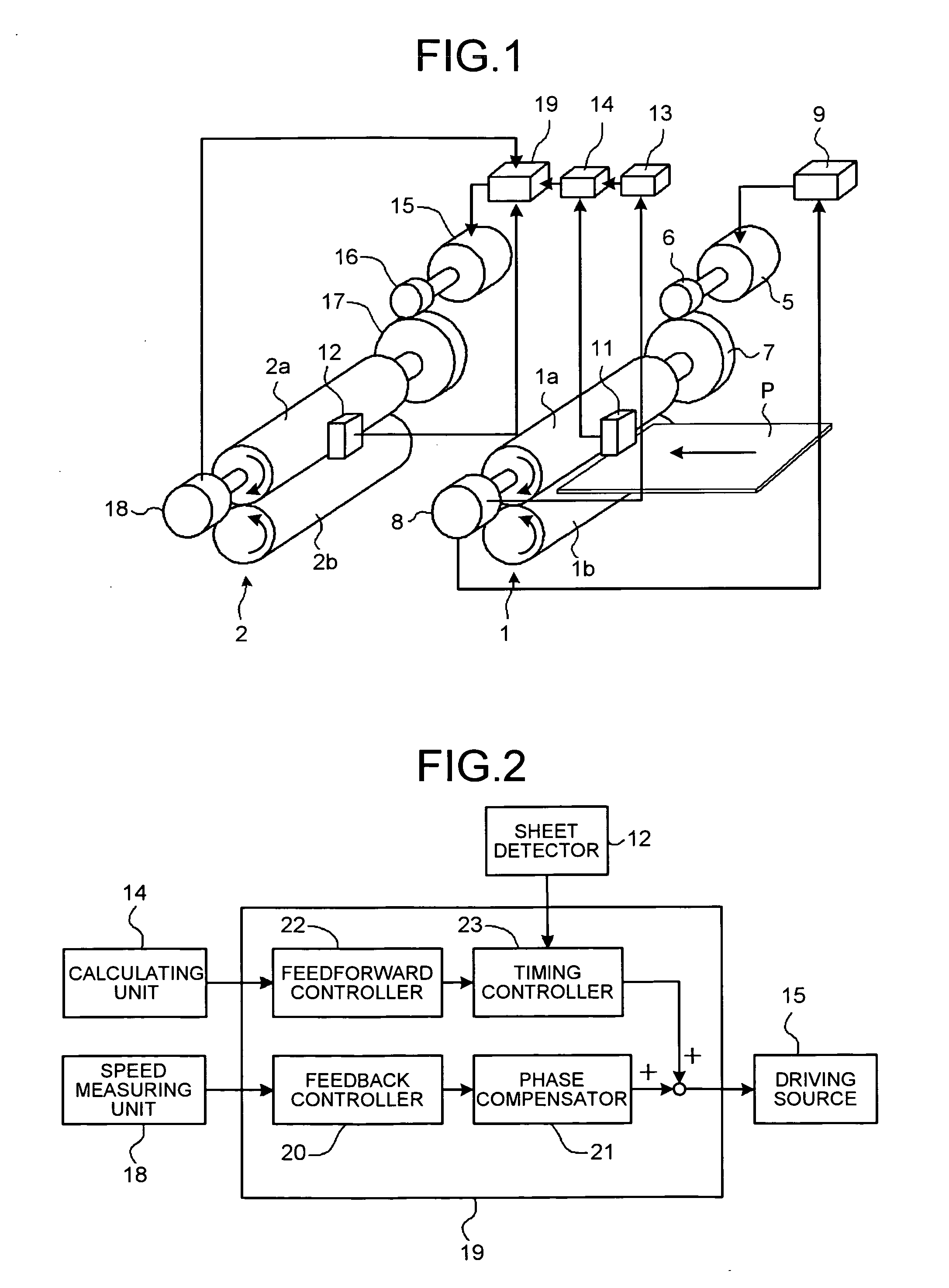
[0033]FIG. 1 is a schematic diagram of a sheet conveying device according to a first embodiment of the present invention. The sheet conveying device of the first embodiment includes a pair of upstream rollers 1 as a first sheet conveying unit and a pair of downstream rollers 2 as a second sheet conveying unit. The pairs of rollers 1 and 2 each includes a drive roller 1a and a driven roller 1b, a drive roller 2a and a driven roller 2b. Sheet detectors 11 and 12 are respectively arranged near this side of the pairs of rollers 1 and 2. A recording medium (sheet) P is held between each pair of rollers 1 and 2, and conveyed from right to left in FIG. 1. The sheet conveying device can include three or more sheet conveying units.

[0034]The drive roller la in the upstream rollers 1 is driven by a motor (driving source) 5 via a small-diameter gear 6 and a large-diamet...


PUM

PropertyMeasurementUnit
Lengthaaaaaaaaaa
Speedaaaaaaaaaa

Abstract

A sheet conveying device includes a pair of upstream rollers and a pair of downstream rollers each including a drive roller and a driven roller, a calculating unit, and a control unit. The upstream rollers include a measuring unit that obtains speed information of the upstream rollers. The calculating unit calculates a target value based on the speed information. The control unit controls the speed of the drive roller of the downstream rollers based on the target value.

Description

CROSS-REFERENCE TO RELATED APPLICATIONS[0001]The present application claims priority to and incorporates by reference the entire contents of Japanese priority documents 2007-074551 filed in Japan on Mar. 22, 2007 and 2007-288547 filed in Japan on Nov. 6, 2007.BACKGROUND OF THE INVENTION[0002]1. Field of the Invention[0003]The present invention relates to a sheet conveying device and an image forming apparatus.[0004]2. Description of the Related Art[0005]Intermediate transfer type color image forming apparatuses are widespread in use. In such image forming apparatuses, a toner image each formed on a photosensitive element is primarily transferred onto an intermediate transfer member, and a color image on the intermediate transfer member is secondarily transferred onto a recording medium (sheet). The image forming apparatuses can be used for various types of sheet media such as thin sheet, thick sheet, postcard, and envelope, and therefore has an advantage of having high versatility. ...

Claims


Application Information

Patent Timeline
IPC IPC(8): G03G15/00B65H5/34B65H7/02B65H5/02
CPCB65H5/062B65H7/20G03G2215/00746G03G15/6529B65H2801/06B65H2557/23B65H2513/50B65H2513/10B65H2404/143B65H2301/4474B65H2220/02B65H2220/01B65H2220/09B65H2220/03
Inventor NOGUCHI, HIDETAKAANDOH, TOSHIYUKIHOSHINO, SEIJIHODOSHIMA, TAKASHIOIKAWA, TATSUHIKOMATSUDA, HIROMICHIKOMATSU, MAKOTOHASHIMOTO, TAKASHI
Owner RICOH KK
Why Eureka
Try Eureka