
In situ patellar fixing system

Active Publication Date: 2008-09-18
VIANT AS&O HLDG LLC
View PDF11 Cites 35 Cited by
  • Summary
  • Abstract
  • Description
  • Claims
  • Application Information

AI Technical Summary

Benefits of technology

[0006]The present invention is a patellar fixing system for use, for example, in a total knee surgical procedure. The fixing system stabilizes a patella in situ in spatial / physical reference to the femoral prosthesis (or the femoral trial) to enable the appropriate cut to be made to the patella to assure the accuracy of the cutting / resurfacing of the patella to accommodate the patello-femoral gap at the replacement knee joint. The present system for resecting a patella in situ comprises a patella jig and a referencing component. The patella jig incorporates a patella clamp mechanism adapted to releaseably hold the patella. The femur referencing or engaging component provides a connection between the patella jig and an anchor point or landmark (i.e., a reference feature) on the femur. The connection to the anchor point or reference feature on the femur enables the patella jig to be oriented relative to the reference feature. Thus a patella held in the clamp mechanism can be fixed in an appropriate orientation relative to the femur during its resection. Cutting the patella while it is referenced to the patellar groove on the femur increases the accuracy of the resection relative to what otherwise may be accomplished.

Problems solved by technology

However, there is a present controversy as to whether during a knee joint replacement surgery, the patella should be replaced as well.
The controversy is difficult to resolve, because the patella replacement portion of a total knee replacement operation is the most poorly performed and understood aspect of the surgery.
The reason for this is at least in part because of the lack of appropriate alternative patellar jigs to guide the surgeon when replacing / resurfacing the patella.
Because the patella is cut / resurfaced in isolation, it is difficult to easily assure the accuracy of the cutting / resurfacing of the patella to accommodate the flexion gap, the extension gap and the patello-femoral gap at the replacement knee joint.

Method used


Image

  • In situ patellar fixing system
  • In situ patellar fixing system
  • In situ patellar fixing system

Examples


Embodiment Construction

[0015]Referring now to the drawings, the details of preferred embodiments of the present invention are graphically and schematically illustrated. Like elements in the drawings are represented by like numbers, and any similar elements are represented by like numbers with a different lower case letter suffix.

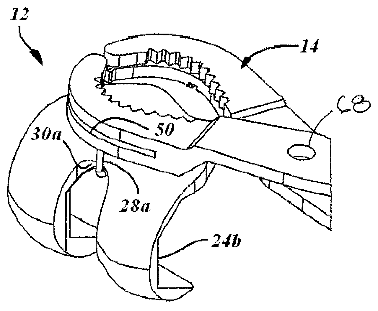
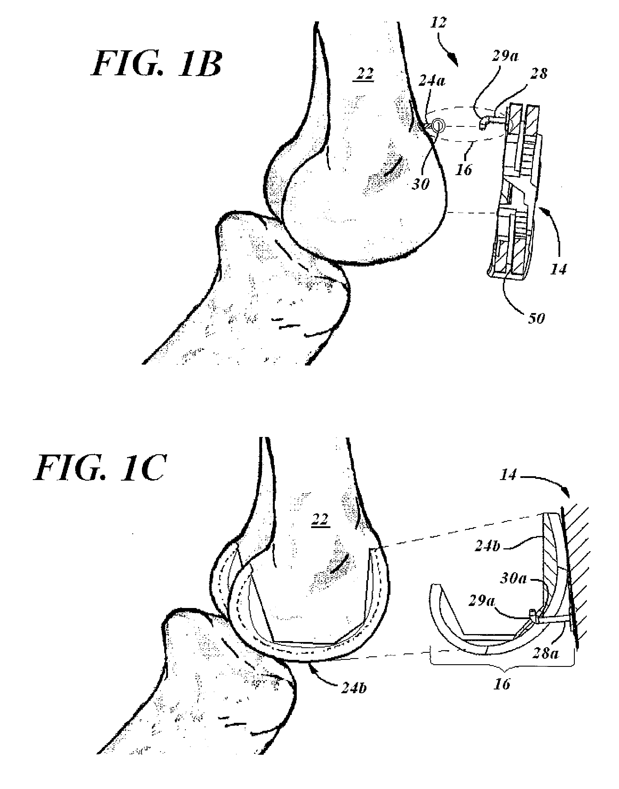
[0016]As exemplified in FIG. 1A, the present invention is an patellar fixing system 10 for use in situ in resecting a patella 20, in surgical procedures such as a knee joint replacement surgery. The system 10 includes a patella jig 12 comprised of a patella clamp mechanism 14 and a femur engaging component 16. The clamp mechanism 14 is adapted to releaseably grip and hold the patella 20 during its resection. Patella clamping mechanisms are known in the art. The femur engaging component 16 is adapted to interface with a femur reference feature 24 on a femur 22 and serves to connect the patella jig 14 to the reference feature 24. This connection allows the clamping mechanism 14 of t...


PUM


Abstract

Disclosed is a patellar cutting jig for use in a knee joint surgical procedure. The jig grips and holds a patella in situ in spatial reference to the femur to enable the appropriate cut to be made to the patella to accurately accommodate the patello-femoral gap at the replacement knee joint. The patella jig has a referencing component that provides a landmark connection between the patella jig and the femur which enables the patella clamp of the jig to be oriented relative to the reference feature prior to gripping the patella. Thus a patella held in the clamp is fixed in the cutting jig an appropriate orientation relative to the femur prior to its resection. Cutting the patella while it is referenced to the patellar groove on the femur increases the accuracy of the resection.

Description

[0001]The present application claims the benefit of prior filed U.S. Provisional application Ser. No. 60 / 892,629, filed 2 Mar. 2007, which application is incorporated herein by reference.FIELD OF THE INVENTION[0002]The present invention is in the field of surgical apparatuses used in the treatment of diseases, wounds and other abnormal conditions of the bodies of humans and lower animal (Class 128). Specifically, the present invention relates to orthopedic instrumentation designed for particular use in a surgical procedure on bone structure to correct a deformity, fracture, unwanted or diseased condition Class 606 / subclass 53). More specifically, the present invention relates to an osteotomy jig for use in bone reparation, to align a cutting means in a desired orientation for severing or partially severing a bone at a knee / knee joint so that a prosthetic member fitted thereto to effect the repair of the bone (subclasses 86-88).BACKGROUND OF THE INVENTION[0003]Total knee joint replac...

Claims


Application Information

Patent Timeline
IPC IPC(8): A61B17/58A61F5/00
CPCA61F2/3859A61B17/158
Inventor SHERRY, EUGENESIVANANTHAN, SURESHANWARNKE, PATRICK HANS HEINRICHWHITE, PATRICKCHENAUX, FABRICE
Owner VIANT AS&O HLDG LLC
Learn More