
Systems and Methods for Dynamically Managing Virtual Machines

a virtual machine and dynamic management technology, applied in the field of virtual machine environments, can solve the problems of large number of heterogeneous servers, application and often gross underutilization of information technology (it) environments, and achieve the effects of large heterogeneous servers, large application and large application spa

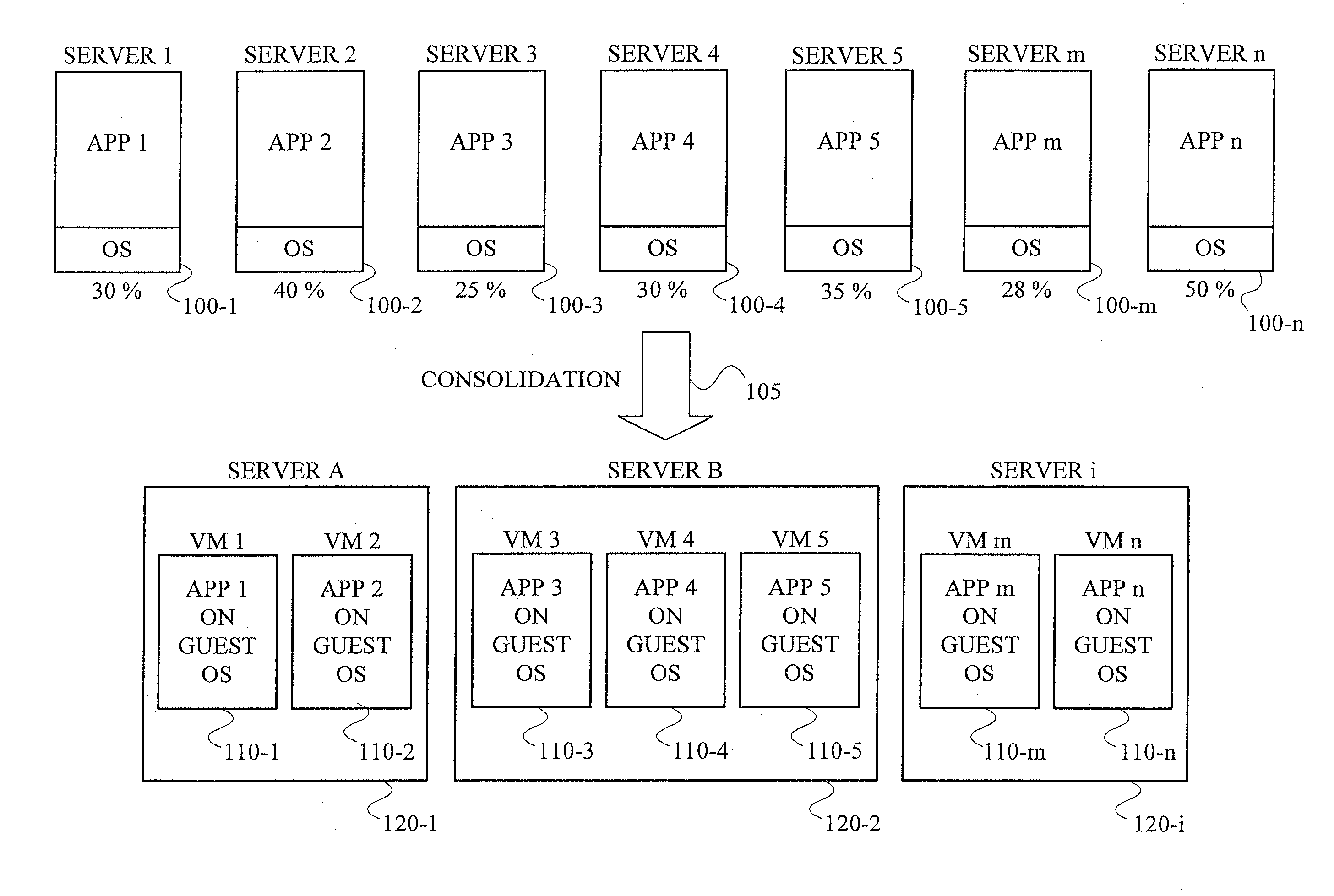
Active Publication Date: 2008-09-11
SERVICENOW INC
View PDF14 Cites 95 Cited by
  • Summary
  • Abstract
  • Description
  • Claims
  • Application Information

AI Technical Summary

Benefits of technology

The present invention provides techniques for managing virtual machine environments in real-time to ensure optimal performance and cost-effectiveness. Specifically, the invention allows for automatic management of virtual machines hosted on physical machines based on performance measurements and migration costs. The technical effect of this invention is improved management of virtual machine environments, leading to better performance and cost-effectiveness.

Problems solved by technology

An important problem encountered in today's information technology (IT) environment is known as server sprawl.
Because of unplanned growth, many data centers today have large numbers of heterogeneous servers, each hosting one application and often grossly under utilized.
There are some critical runtime issues associated with a consolidated server environment.
For example, due to user application workload changes or fluctuations, a critical problem often arises in these environments.
The critical problem is that end user application performance degrades due to over utilization of critical resources in some of the physical machines.
Accordingly, an existing allocation of VMs to physical machines may no longer satisfy service level agreement (SLA) requirements.
However, such a reallocation has an associated migration cost.
Existing consolidation approaches do not account for the cost of migration.

Method used


Image

  • Systems and Methods for Dynamically Managing Virtual Machines
  • Systems and Methods for Dynamically Managing Virtual Machines
  • Systems and Methods for Dynamically Managing Virtual Machines

Examples


Embodiment Construction

[0014]The following description will illustrate the invention using an exemplary SLA-based service provider environment. It should be understood, however, that the invention is not limited to use with such a particular environment. The invention is instead more generally applicable to any data processing or computing environment in which it would be desirable to manage virtual servers used to perform such data processing or computing operations.

[0015]It is to be appreciated that, as used herein, a “physical machine” or “physical server” refers to an actual computing device, while a “virtual machine” or “virtual server” refers to a logical object that acts as a physical machine. In one embodiment, the computing device may be a Blade™ available from International Business Machines Corporation (Armonk, N.Y.). A Blade™ includes a “thin” software layer called a Hypervisor™, which creates the virtual machine. A physical machine equipped with a Hypervisor™ can create multiple virtual machi...


PUM


Abstract

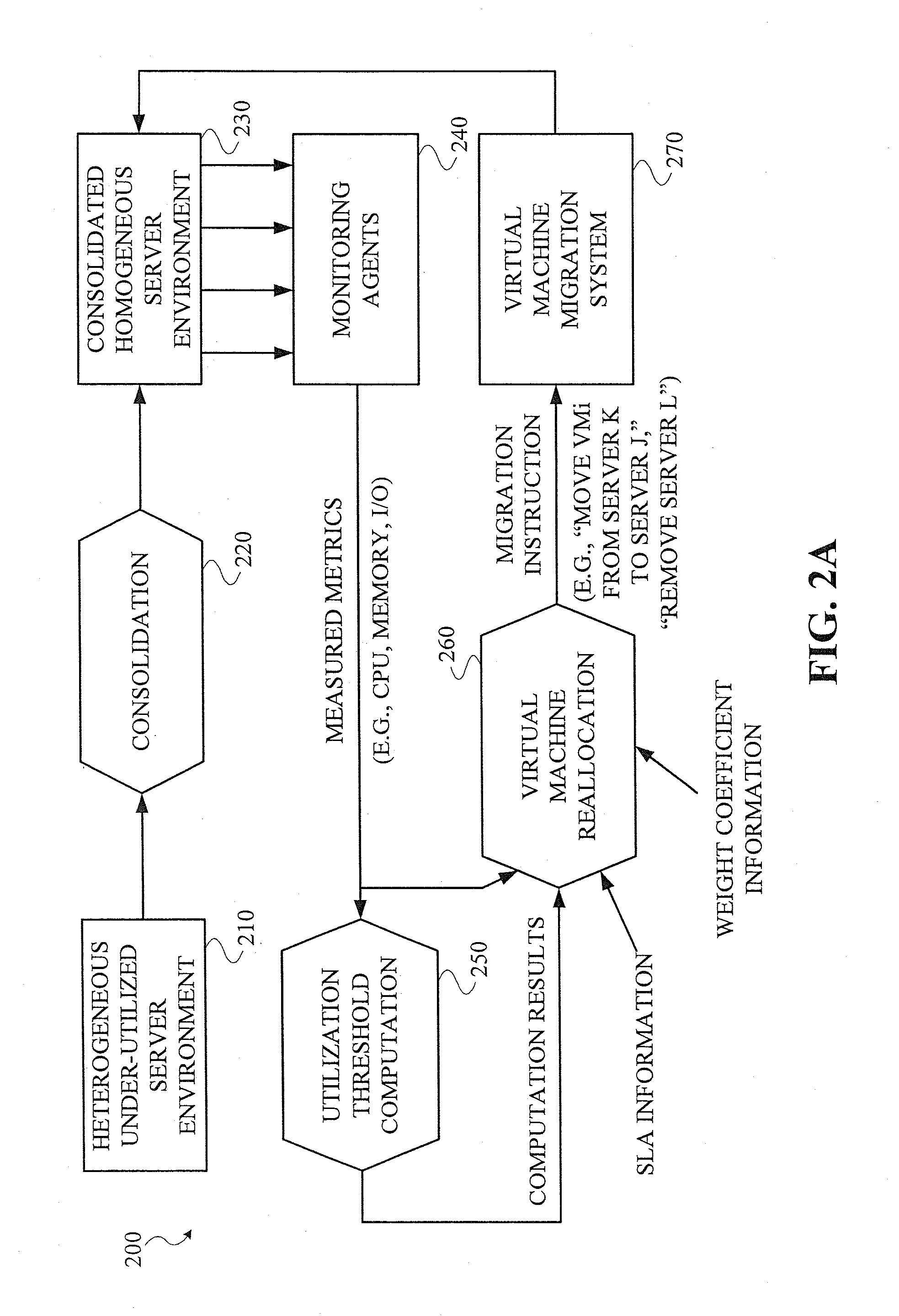
Techniques for dynamic management of virtual machine environments are disclosed. For example, a technique for automatically managing a first set of virtual machines being hosted by a second set of physical machines comprises the following steps / operations. An alert is obtained that a service level agreement (SLA) pertaining to at least one application being hosted by at least one of the virtual machines in the first set of virtual machines is being violated. Upon obtaining the SLA violation alert, the technique obtains at least one performance measurement for at least a portion of the machines in at least one of the first set of virtual machines and the second set of physical machines, and a cost of migration for at least a portion of the virtual machines in the first set of virtual machines. Based on the obtained performance measurements and the obtained migration costs, an optimal migration policy is determined for moving the virtual machine hosting the at least one application to another physical machine.

Description

CROSS-REFERENCE TO RELATED APPLICATION(S)[0001]This application is a continuation of pending U.S. application Ser. No. 11 / 364,449 filed on Feb. 28, 2006, the disclosure of which is incorporated herein by reference.FIELD OF THE INVENTION[0002]This present invention generally relates to virtual machine environments and, more particularly, to techniques for dynamically managing virtual machines.BACKGROUND OF THE INVENTION[0003]An important problem encountered in today's information technology (IT) environment is known as server sprawl. Because of unplanned growth, many data centers today have large numbers of heterogeneous servers, each hosting one application and often grossly under utilized.[0004]A solution to this problem is a technique known as server consolidation. In general, server consolidation involves converting each physical server or physical machine into a virtual server or virtual machine (VM), and then mapping multiple VMs to a physical machine, thus increasing utilizati...

Claims


Application Information

Patent Timeline
Patent Type & Authority Applications(United States)
IPC IPC(8): G06F9/46
CPCG06F2009/4557G06F9/45558
Inventor BEATY, KIRK A.BOBROFF, NORMANKAR, GAUTAMKHANNA, GUNJANKOCHUT, ANDRZEJ
Owner SERVICENOW INC
Learn More