
Vehicle control system and method using control allocation and phase compensation

a control system and vehicle technology, applied in adaptive control, process and machine control, instruments, etc., can solve the problems of inability to meet input, inability to adapt to distribution, and inability to move the control surface freely

Inactive Publication Date: 2008-09-04
SAAB AB
View PDF14 Cites 4 Cited by
  • Summary
  • Abstract
  • Description
  • Claims
  • Application Information

AI Technical Summary

Benefits of technology

[0015]The estimated motion behavior y′ calculated from actuator commands x, may not be the same as the one demanded by input signals u. The time derivative of x1 to xm limited in these cases. It is however an advantage that a limited time der

Problems solved by technology

In particular it relates to methods and apparatus for improving performance and stability in a control system where the time derivative of an output from a subsystem is limited, resulting in that an input cannot be fulfilled.
In this case the distribution will not be able to adapt to varying effectiveness of the different actuators throughout the envelop of the controlled system.
Such faults may include loss, i.e., control surface moves freely, and locking i.e., control surface gets stuck in an arbitrary position.
Prior art control allocation systems have a tendency to build up an undesired phase loss, when said control allocation systems together with available actuators no longer are able to fulfil current control demand.
Non-considered phase loss in a regulatory system is highly undesired.
However, this solution takes care of one actuator at a time.

Method used


Image

  • Vehicle control system and method using control allocation and phase compensation
  • Vehicle control system and method using control allocation and phase compensation
  • Vehicle control system and method using control allocation and phase compensation

Examples


Embodiment Construction

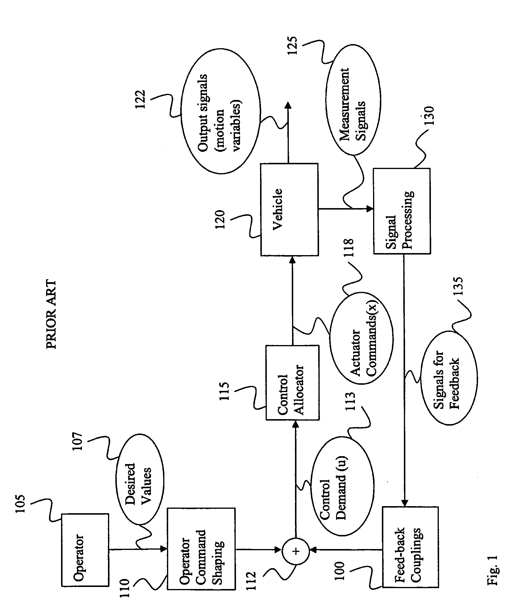
[0050]FIG. 1 shows a block diagram, demonstrating signal flow within a vehicle control allocation control system according to known technology. An operator, e.g., a pilot 105 or a travel control unit of an autonomous vehicle communicates desired values of vehicle state or waypoints or reference values in speed, altitude and course to the vehicle control system by some means e.g. by control stick movements, pedal movements or by conveying suitable signals, as in the case with an autonomous vehicle. The travel control system comprises an Operator Command Shaping Unit 110 that receives said desired values and filters them.

[0051]The filtered desired values are subsequently fed to a summation unit 112—In the summation unit 112 feedback signals and the filtered desired values are added together forming a sum. The sum may e.g. represent ordered angular accelerations of vehicle attitude angles. A control allocator 115 translates the ordered angular accelerations of vehicle attitude angles i...


PUM


Abstract

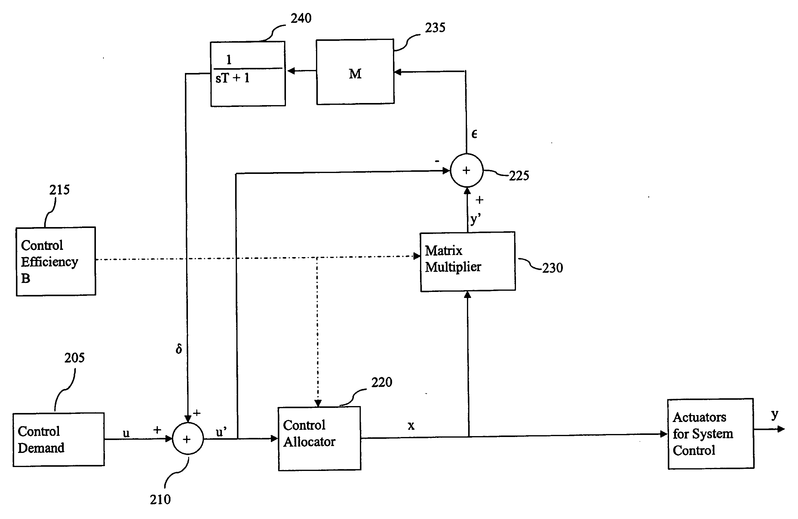
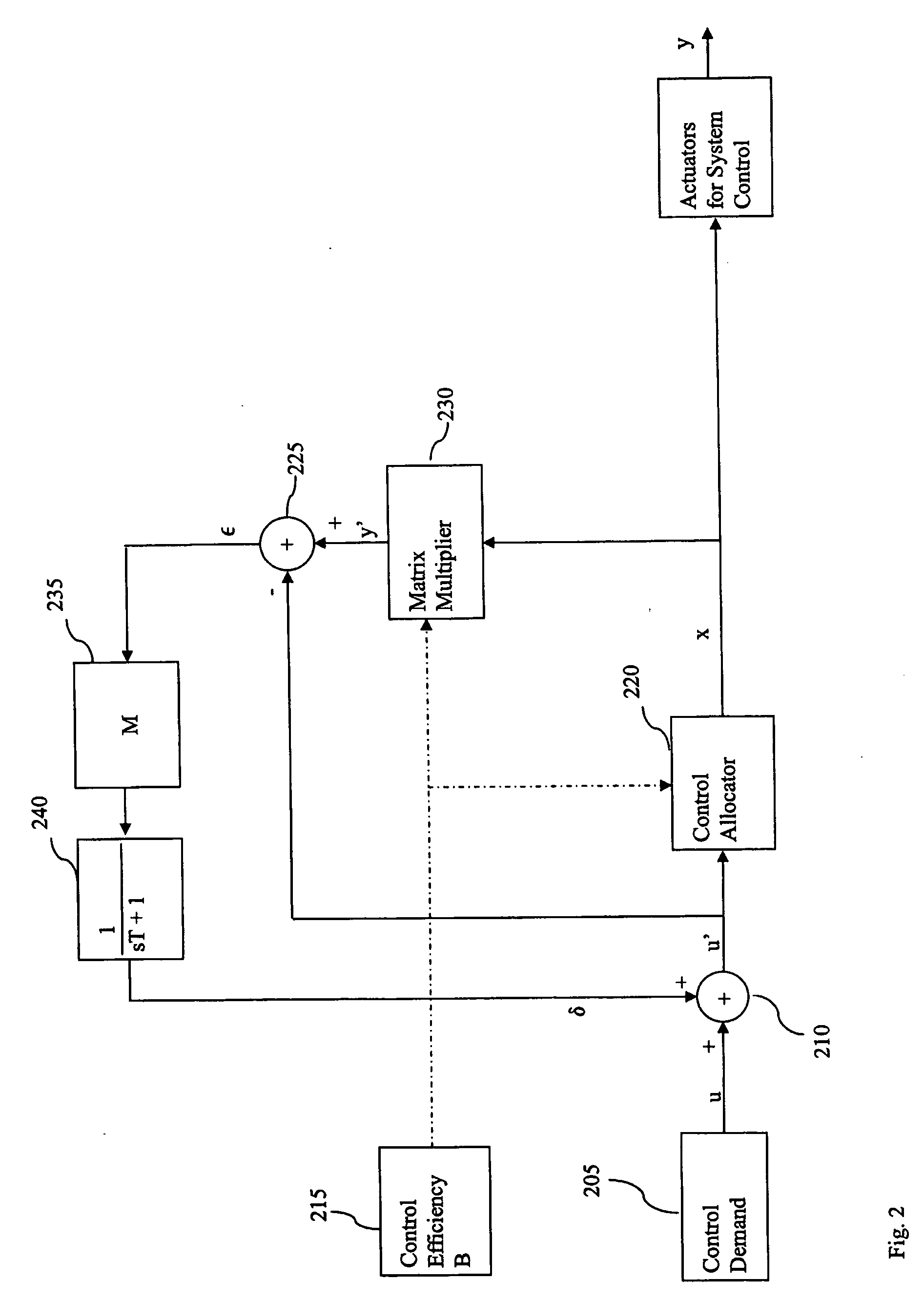
A vehicle control system and method combining control allocation and phase compensation for forming a phase compensated actuator command signal based on a control demand signal. A feedback unit includes a matrix multiplication unit for forming an estimated behaviour signal, from a control efficiency matrix and the actuator command signal. The estimated behaviour signal is fed to a second summation unit for forming a difference signal. The difference signal from the summation unit is processed by a filter unit for forming a feedback signal which is connected to a first summation unit for forming a modified control demand signal, such that the modified control demand signal is adjusted to always represent a control demand realisable by the vehicle. The modified control demand signal of the first summation unit is further connected to the second summation unit and to a control allocator which output is then connected to the matrix multiplier to form a feedback loop.

Description

TECHNICAL FIELD[0001]The present invention relates to the field of vehicle control. In particular it relates to methods and apparatus for improving performance and stability in a control system where the time derivative of an output from a subsystem is limited, resulting in that an input cannot be fulfilled. More particularly it relates to such methods and apparatus for improving control systems provided with some kind of control allocation.BACKGROUND[0002]In control theory and praxis, a control system of a vehicle can be viewed upon as a system performing two subsequent separate steps;[0003]a first step comprising calculating a control demand based on operator commands and feedback signals and taking into consideration requirements on stability and performance; and[0004]a second step comprising calculating and distributing actuator signals to the available actuators, based on the control demand, such that said control demand will be realised. A more detailed explanation can be foun...

Claims


Application Information

Patent Timeline
IPC IPC(8): G06F17/00
CPCG05B13/021G05B13/02G05B13/041B60K31/00G05B13/024
Inventor SUNDQVIST, BENGT-GORAN
Owner SAAB AB
Learn More