
Graphical user interface for telephony device

a telephony device and user interface technology, applied in the field of telephony devices, can solve the problems of confusing and time-consuming toggling between windows, disrupting the user's activities in connection with such obscured windows, and reducing the annoyance of users in the way the telephony application behaves, so as to reduce eliminate the annoyance of users, and facilitate the management of phone calls

Inactive Publication Date: 2008-09-04
MITEL
View PDF9 Cites 4 Cited by
  • Summary
  • Abstract
  • Description
  • Claims
  • Application Information

AI Technical Summary

Benefits of technology

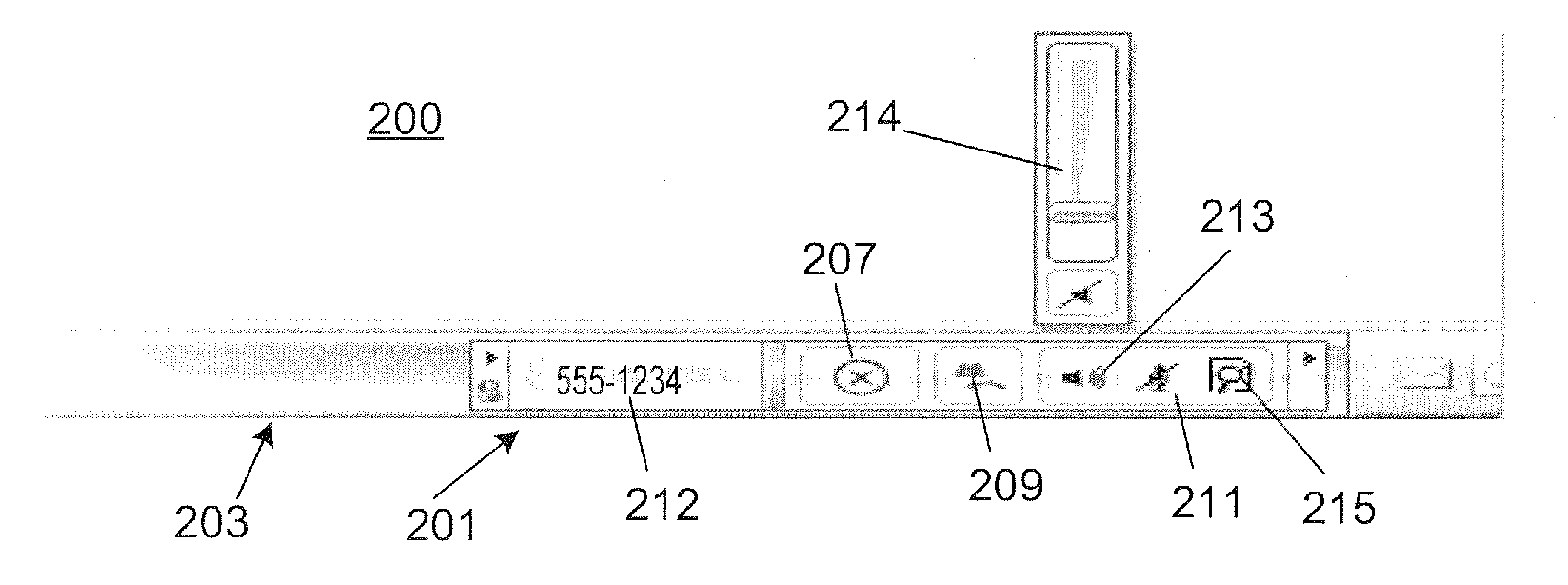
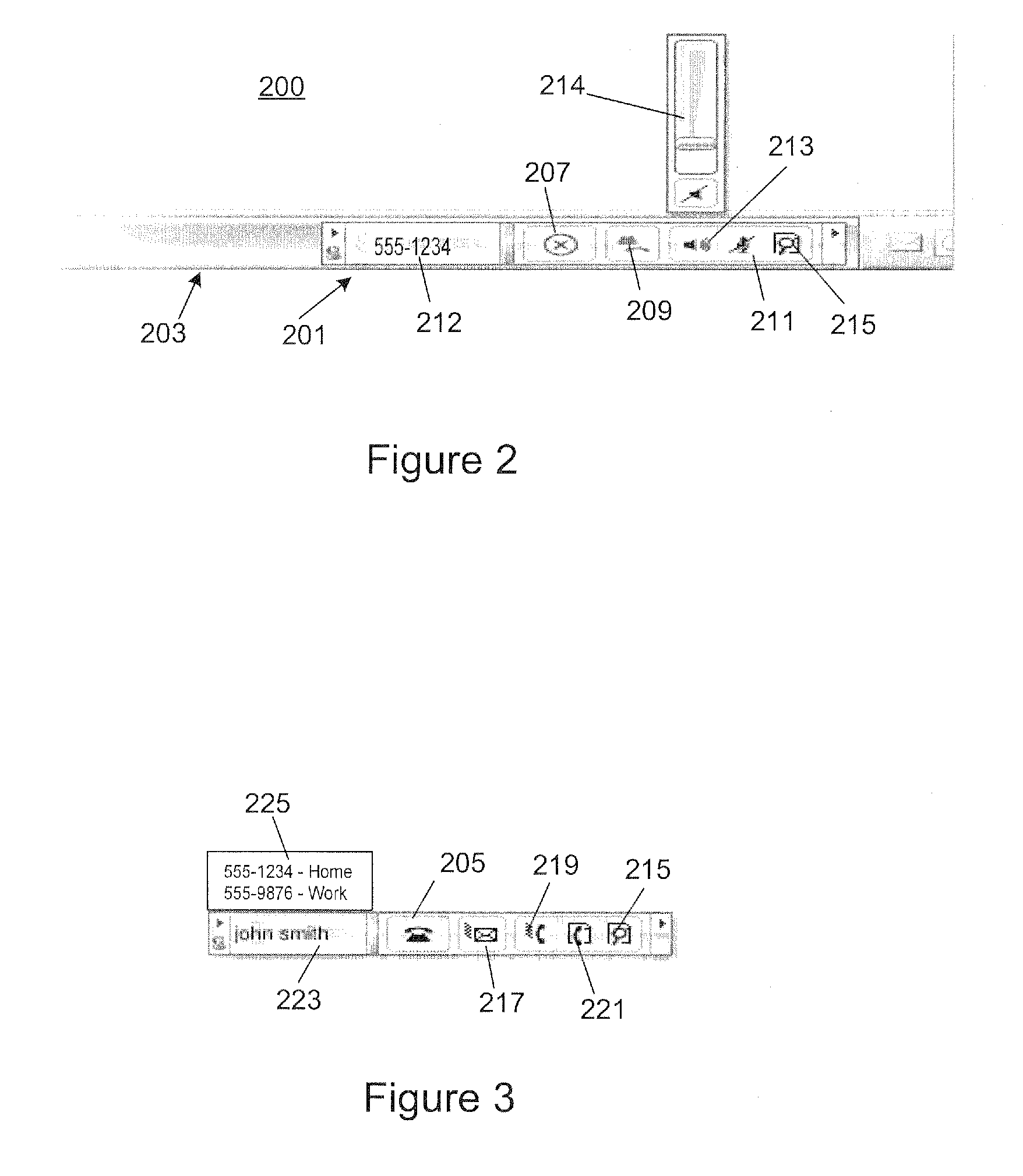
[0007]According to the present invention, a telephony application GUI is provided for display on a computer such as a PC or laptop, that does not cover up any existing application windows when a call is received or when the user wishes to place a call or manage an existing call. The application GUI remains visible and accessible to the user regardless of what application the user is currently using. In this way, the obtrusiveness of incoming calls is minimized, eliminating much of the annoyance that users associate with existing telephony applications. According to one aspect, the application GUI provides context sensitive buttons for call handling functions that allow the user to easily manage their phone calls. According to another aspect, the telephony application GUI allows the user to look up phone numbers by typing in a contact name that has been stored in a local or networked contact management application, without opening a window for that application. Numbers returned for the contact appear within the application GUI for selection and dialing. According to yet a further aspect, caller ID information is displayed to the user for incoming calls, without the use of a toast pop window. The caller ID information appears within the application GUI and does not cover up any other windows on the user's computer screen.

Problems solved by technology

This is very disruptive to the user and may lead to user annoyance in the way the telephony application behaves.
However, once the telephony control window opens it typically obscures other windows open on the user's PC screen thereby disrupting the user's activities in connection with such obscured windows.
Toggling back and forth between windows can be both confusing and time consuming and makes call handling difficult while accessing features of underlying application windows.

Method used


Image

  • Graphical user interface for telephony device
  • Graphical user interface for telephony device
  • Graphical user interface for telephony device

Examples


Embodiment Construction

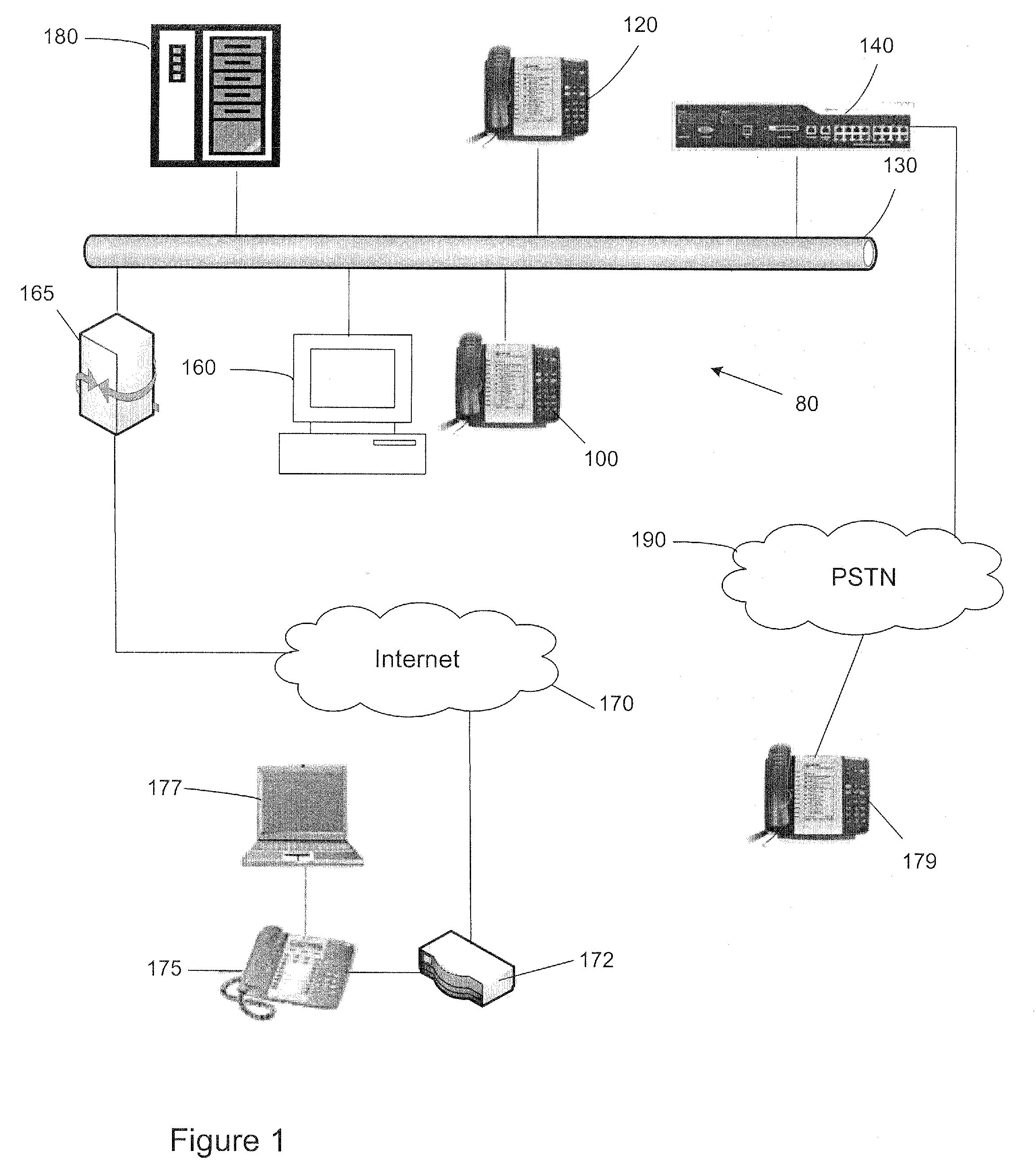
[0013]Reference is first made to FIG. 1 showing an enterprise communication system 80 forming an exemplary environment for implementation of the telephony application GUI of the present invention. A first telephone device 100 (i.e. IP phone) of a first user and a second telephone device 120 of a second user are both connected via a local area network 130 to a telephony switch 140 that is responsible for telephony connections between the first telephone device 100 and the second telephone device 120, as well as outside connections to a telephone device 179 over the PSTN 190. The first telephone device 100 is associated with a PC 160 having software for communicating with the telephony switch 140 over LAN 130 (or directly connected to telephony device 100 using suitable APIs), such as a PC based telephony application to control collaborative communication features of the device 100 and PC 160 (e.g. Microsoft® Office Communicator). The user at telephone device 100 uses PC 160 to activa...


PUM


Abstract

For use with a telephony application executed within a computer having a screen display, the improvement comprising displaying a tool bar having at least one context sensitive button within a task bar on the screen display, wherein the tool bar is located so as not to overlap any application windows displayed on the screen display.

Description

BACKGROUND OF THE INVENTION[0001]1. Field of the Invention[0002]The present invention is directed to telephony devices, and more particularly to a graphical user interface for use on a telephony device.[0003]2. Description of the Related Art[0004]PC based telephony applications are well known in the art, most of which provide a Graphical User Interface (GUI) based on the typical Windows® method of display (i.e. the application GUI appears in a window on the PC screen similar to all of the other applications on the screen). Because telephony applications operate within standard application windows, they behave in the same manner, namely when the application is active or in focus, its window covers up other application windows on the user's screen. This method of operation has been designed around a methodology that assumes that the user decides which window (application) they want to have active or on top of other windows.[0005]Telephony applications differ from most other applicatio...

Claims


Application Information

Patent Timeline
Patent Type & Authority Applications(United States)
IPC IPC(8): H04M3/42
CPCH04M1/2473H04M1/2535H04M2201/42H04M7/0012H04M1/57
Inventor COUSE, PETER FRANCIS
Owner MITEL
Learn More