
Image developer, process cartridge and image forming apparatus

Inactive Publication Date: 2008-08-28
RICOH KK
View PDF12 Cites 11 Cited by
  • Summary
  • Abstract
  • Description
  • Claims
  • Application Information

AI Technical Summary

Benefits of technology

[0013]Accordingly, an object of the present invention is to provide a downsized image developer longitudinally having a developer container above a developer charging and layer forming part thereof, capable of stably feeding a developer to the developer charging and layer forming part to develop quality images.

Problems solved by technology

However, the image developer in which a developer charging and layer forming part and a developer storing part are located in parallel as disclosed in Japanese Patent No. 3320954 is difficult to downsize, and particularly the full-color image forming apparatus having plural image forming units are more difficult to downsize.
The developer is fed in the direction of gravitational force and an intake capacity of the developer varies a feeding amount thereof and it is difficult to stably feed the developer, resulting in foggy images due to an excessive uncharged developer and defective images such as image density variation.
When the apparatus is not used or left for a while, the developer in the image developer agglutinates due to gravity and only the toner very close to the feeding roller and developing roller is used, resulting in image density deterioration and hazy images due to poor feeding of the toner.
However, the toner is difficult to transfer up and down in the vertically long image developer, the toner is unnecessarily stressed and deterioration thereof is accelerated, and the toner circulation close to the feeding roller deteriorates occasionally depending on the stirring direction.
However, 4 sets of parts such as a toner amount detector (sensor) and an electromagnetic clutch controlling the rotation of the toner feeding member are required, resulting in complicated apparatus and cost increase.
However, stress is directly applied thereto unchangeably and the developer having a small particle diameter and low-temperature fixability is not affected thereby.
Under an environment of high temperature and high humidity, image density deterioration and hazy images due to deterioration of fluidity are inevitable.

Method used


Image

  • Image developer, process cartridge and image forming apparatus
  • Image developer, process cartridge and image forming apparatus
  • Image developer, process cartridge and image forming apparatus

Examples


Embodiment Construction

[0038]The present invention provides a downsized image developer longitudinally having a developer container above a developer charging and layer forming part thereof, capable of stably feeding a developer to the developer charging and layer forming part to develop quality images.

[0039]More particularly, the present invention relates to an image developer, comprising:

[0040]a rotatable developer bearer;

[0041]a rotatable developer feeding member contacting the developer bearer;

[0042]a developer container located above the developer feeding member,

[0043]wherein the developer container comprises:

[0044]a pressure reducing member configured to reduce a pressure applied to the developer feeding member;

[0045]a stirring bar configured to stir a developer; and

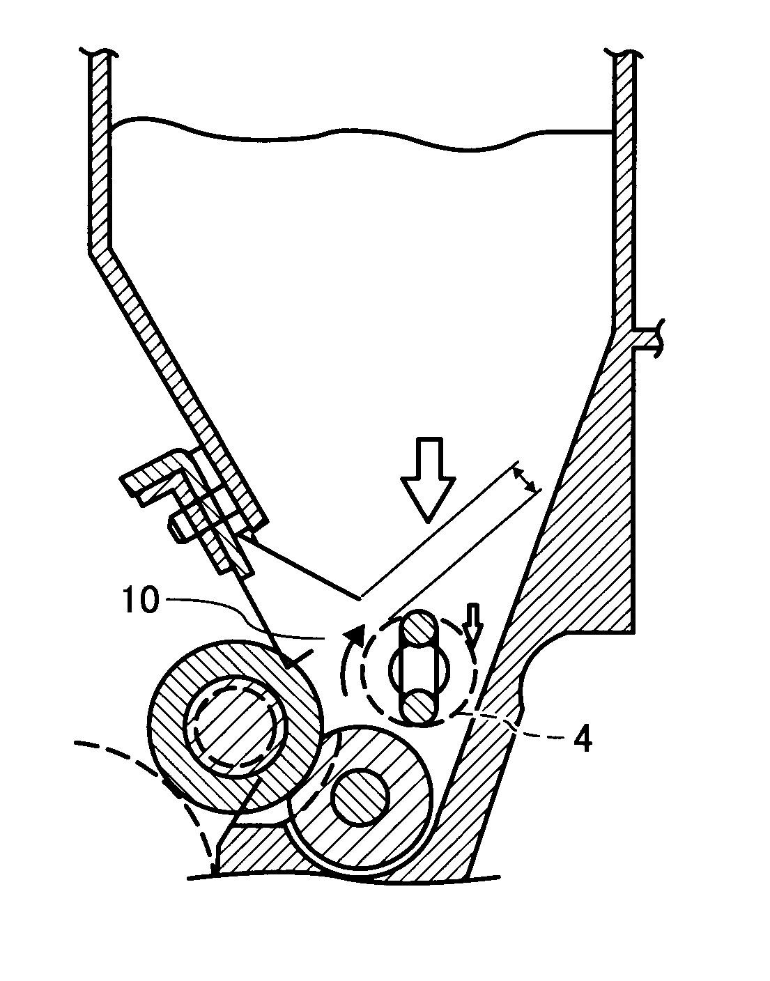
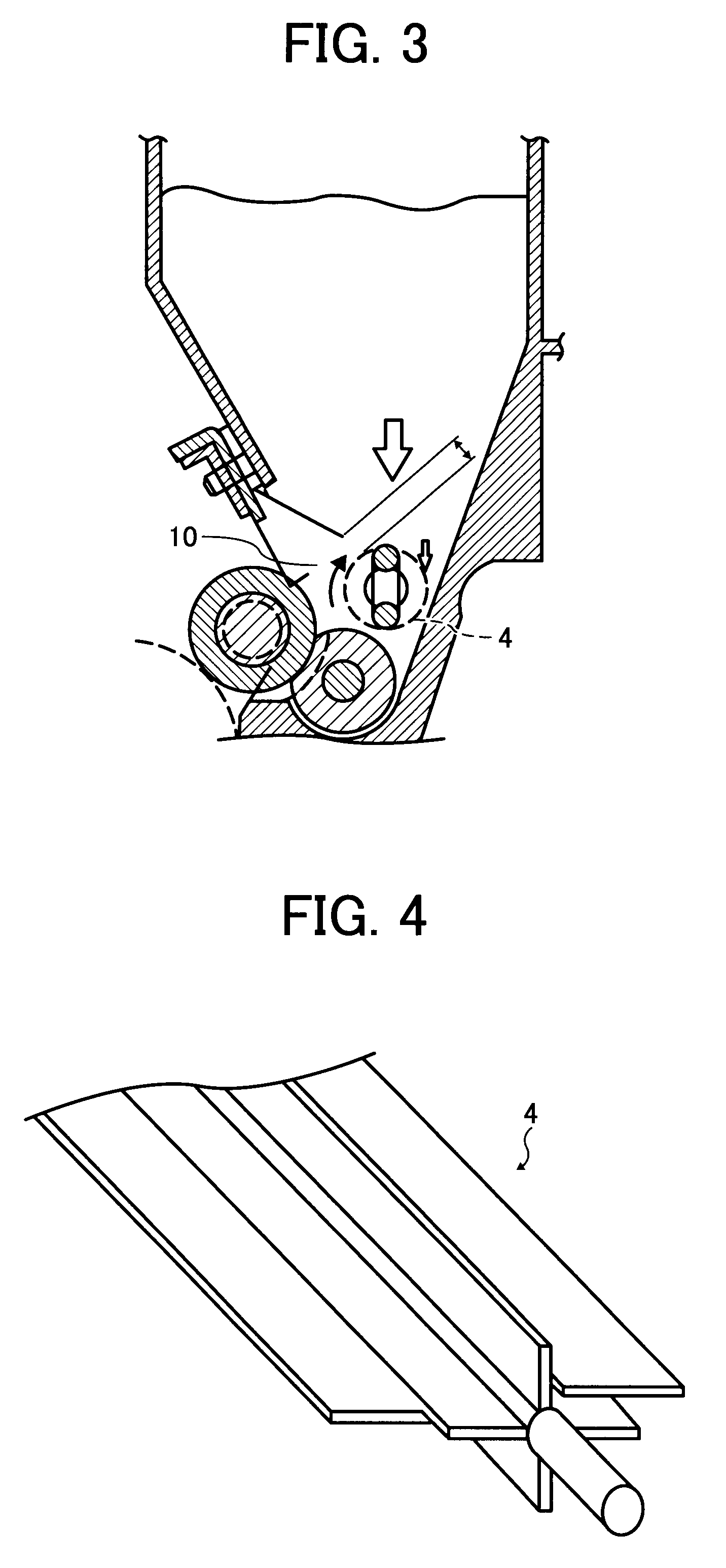
[0046]a gap of 6 mm between an end of the pressure reducing member and an outer diameter of the stirring bar.

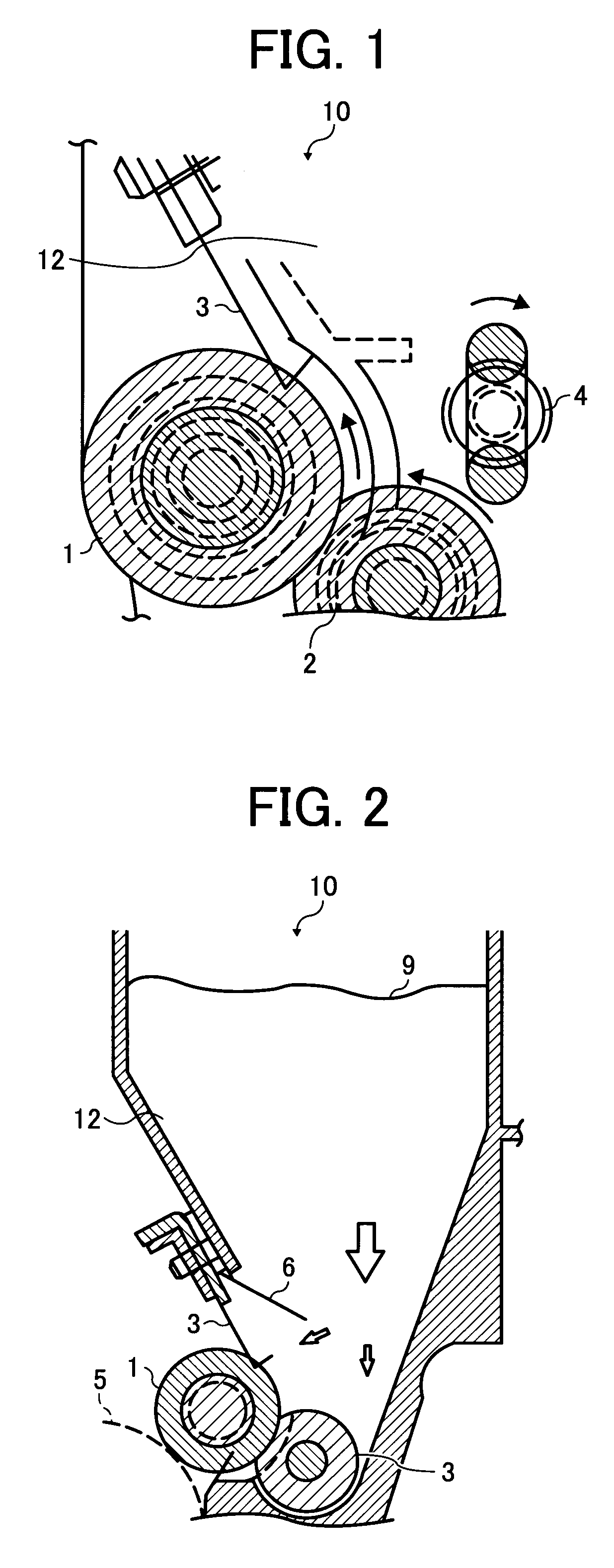
[0047]FIG. 1 is schematic view illustrating a toner flow in an image developer. The toner flows along the rotations of each rota...


PUM


Abstract

An image developer, including a rotatable developer bearer; a rotatable developer feeding member contacting the developer bearer; a developer container located above the developer feeding member, wherein the developer container includes a pressure reducing member configured to reduce a pressure applied to the developer feeding member; and a first stirring bar located directly below the pressure reducing member and configured to stir a developer such that a gap between an end of the pressure reducing member and an outer diameter of the stirring bar is 6 mm.

Description

BACKGROUND OF THE INVENTION[0001]1. Field of the Invention[0002]The present invention relates to a an image developer, a process cartridge and an image forming apparatus for electrophotographic image forming processes in copiers, facsimiles, printers, etc.[0003]2. Discussion of the Background[0004]Conventionally, as disclosed in Japanese Patent No. 3320954, one-component image developer has been known, in which a non-magnetic or a magnetic toner (developer) included in a container is fed to a developing roller (developer bearer) with a toner feeding member (roller) formed of a foamed polyurethane, etc., an elastic member such as a metallic thin plate is pressed to the developing roller (developer bearer) to uniform a toner thereon, and an electrostatic latent image formed on a photoreceptor (image bearer) is developed with toner.[0005]Recently, in compliance with color-oriented demands at offices, full-color image forming apparatuses appear. One of the full-color image forming appar...

Claims


Application Information

Patent Timeline
IPC IPC(8): G03G15/08
CPCG03G15/0877G03G2215/085
Inventor HORI, EISUKEKIMURA, HIDEKI
Owner RICOH KK
Learn More