
User interface device

a user interface and device technology, applied in the field of user interface devices, can solve the problems of user error, many portable electronic devices cannot provide a sufficient space for operation elements, and user may perform an erroneous operation, so as to achieve the effect of reducing the size of a portable electronic device and being convenient to opera

Inactive Publication Date: 2008-08-28
EASTMAN KODAK CO
View PDF0 Cites 101 Cited by
  • Summary
  • Abstract
  • Description
  • Claims
  • Application Information

AI Technical Summary

Benefits of technology

[0011]The present invention is directed to a user interface device which can be easily operated by a user and can reduce the size of a portable electronic device.

Problems solved by technology

To satisfy these requirements, the portable electronic devices cannot provide a sufficient space for operation elements (e.g., manipulation buttons).
However, as described above, many of the portable electronic devices cannot provide a sufficient space for the operation elements.
However, according to this conventional technique, a user may perform an erroneous operation because of complexity of the manipulation on an operation element.
However, the capability of a conventional slide detector is limited to detection of direction, orientation, and distance, such as scrolling of a screen or shifting of a cursor.
Therefore, the conventional slide detector cannot contribute to reduction in the total number of operation elements, although the number of direction buttons may be reduced.
As a result, using a slide detector is not effective in reducing the size of a portable electronic device.
In short, none one of the above-described conventional techniques can reduce the size of a portable electronic device without deteriorating the operability of a portable electronic device.

Method used


Image

  • User interface device
  • User interface device
  • User interface device

Examples


Embodiment Construction

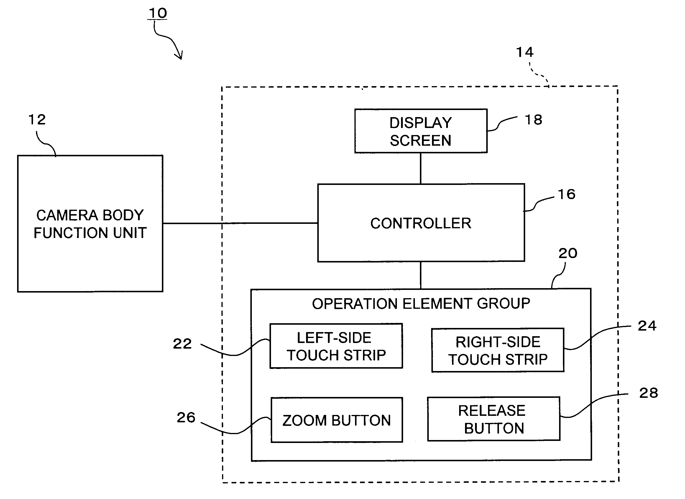
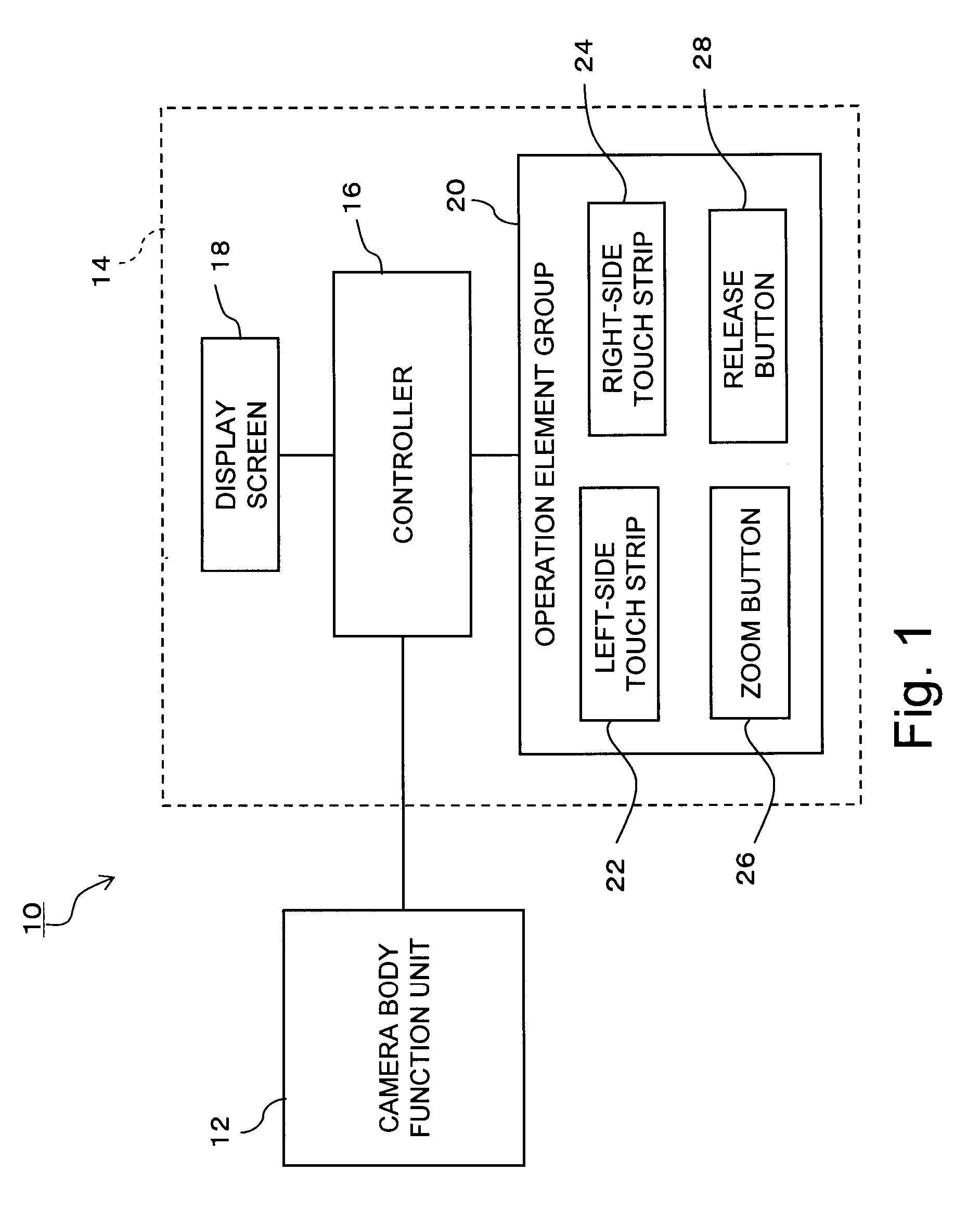
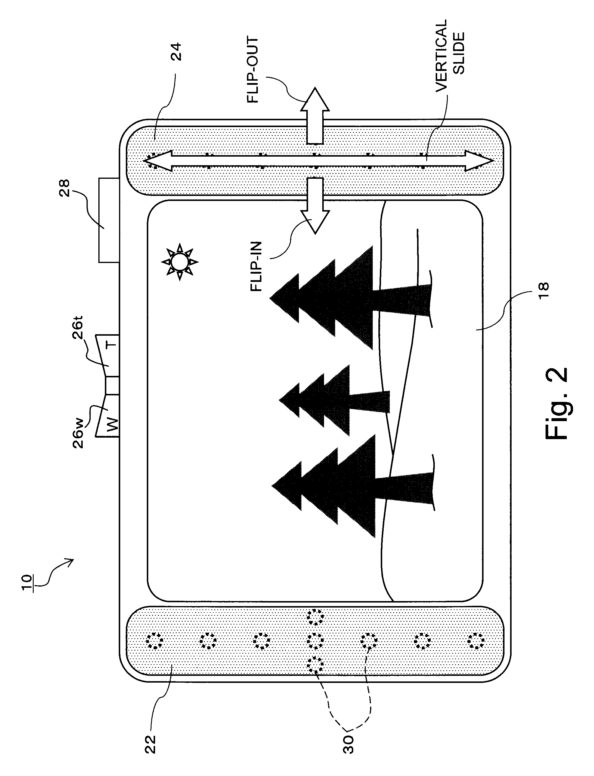
[0027]Exemplary embodiments of the present invention will be described in detail below with reference to the drawings. FIG. 1 is a schematic block diagram illustrating a digital camera 10 according to an embodiment of the present invention. FIG. 2 illustrates a back surface of the digital camera 10.

[0028]The digital camera 10 includes a camera body function unit 12 and a user interface device (hereinafter, referred to as “UI device”) 14. The camera body function unit 12 performs fundamental functions of a camera, such as image pickup processing and image storage processing. Accordingly, the camera body function unit 12 includes an imaging lens, an image pickup element, an image processing circuit, and a memory, whose detailed structures are well known in the prior art.

[0029]The UI device 14 receives a manipulative instruction applied by a user and provides information to a user. The UI device 14 includes a controller 16, a display screen 18, and an operation element group 20. The co...


PUM


Abstract

A UI device of a digital camera has a display screen, a left-side touch strip provided outside of and on a left side of the display screen and a right-side touch strip provided outside of and on a right side of the display screen. The touch strips 22 and 24 can distinguishably detect a slide operation in a vertical direction by the user and a slide operation in a horizontal direction by the user. When a slide operation in the vertical direction is detected, a controller of the UI device recognizes the operation as a manipulative instruction in which the amount of movement is considered important, such as an operation for selection of items or scrolling of a screen. When a slide operation in the horizontal direction is detected, the controller recognizes the slide operation as a triggering manipulative instruction in which the amount of movement is not as important, such as a file deletion instruction or display or non-display of a new hierarchical item.

Description

CROSS REFERENCE TO RELATED APPLICATIONS[0001]This application claims priority to Japanese Patent Application No. 2007-042984 filed on Feb. 22, 2007, which is incorporated herein by reference in its entirety.FIELD OF THE INVENTION[0002]The present invention relates to a user interface device equipped in a portable electronic device which receives an instruction from a user and presents information to a user.BACKGROUND OF THE INVENTION[0003]Various types of portable electronic devices, such as digital cameras and game machines, are widely used and required to be compact enough to improve their portability. On the other hand, a large screen is preferable to display information and data. To satisfy these requirements, the portable electronic devices cannot provide a sufficient space for operation elements (e.g., manipulation buttons).[0004]A large number of operation elements for manipulation or setting are required to realize multiple functions or highly advanced functions of the porta...

Claims


Application Information

Patent Timeline
IPC IPC(8): G09G5/00G06F3/033G06F3/0362G06F3/041G06F3/048G06F3/0485G06F3/0488G06F3/0489
CPCG06F3/0481H04N1/00392H04N1/00413H04N1/00442H04N1/0045H04N1/00458G06F3/03547H04N1/00469H04N5/2251H04N5/232H04N5/23293H04N2101/00G06F2203/0339H04N1/00461H04N23/633H04N23/632
Inventor HIRATA, YOICHISHIBUYA, MASANOBUNAGURA, MASATOITO, MAKOTO
Owner EASTMAN KODAK CO
Learn More