Eureka AIR delivers breakthrough ideas for toughest innovation challenges, trusted by R&D personnel around the world.

Modular active phased array

a phased array, module technology, applied in the direction of antenna details, modular arrays, antennas, etc., can solve the problems of large cost of radar systems, high cost, and high risk of complete antennas being unable to work normally

Active Publication Date: 2008-08-28
NORTHROP GRUMMAN SYST CORP
View PDF25 Cites 279 Cited by
  • Summary
  • Abstract
  • Description
  • Claims
  • Application Information

AI Technical Summary

Problems solved by technology

These radar systems can be very expensive, and one important cost component is replacement parts.
Like the Navy's Cobra Judy program, AESAs have been adapted to a variety of military applications, and are, consequently, subject to hazardous environmental conditions.
For example, a shipboard AESA may be subjected to severe weather as well as enemy fire, and if the AESA is damaged, the entire antenna is likely to stop functioning, which necessitates the replacement of the damaged component(s).
Unfortunately, AESA repair typically occurs in-port, which may severely impact time-on-station.

Method used


Image

  • Modular active phased array
  • Modular active phased array
  • Modular active phased array

Examples


Embodiment Construction

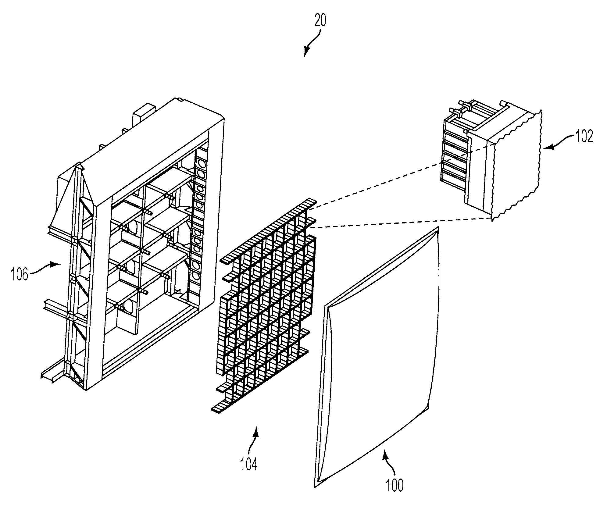
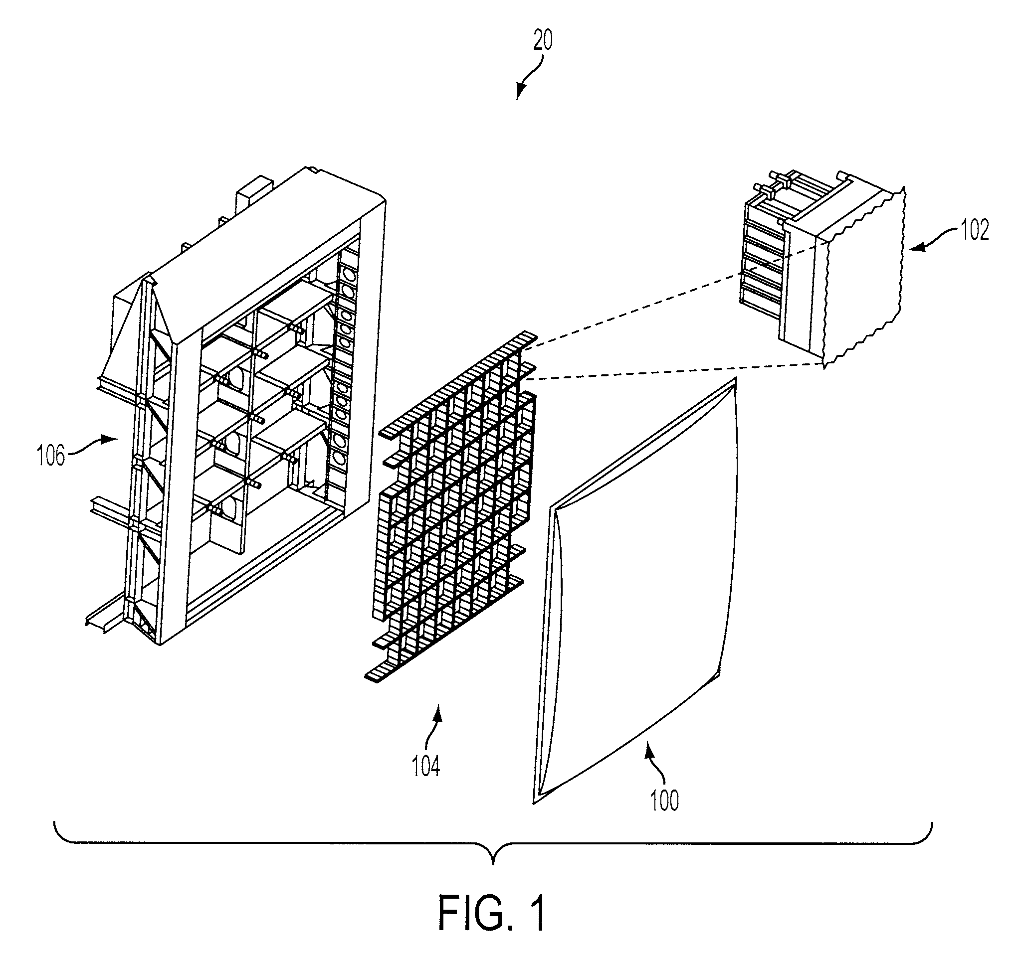
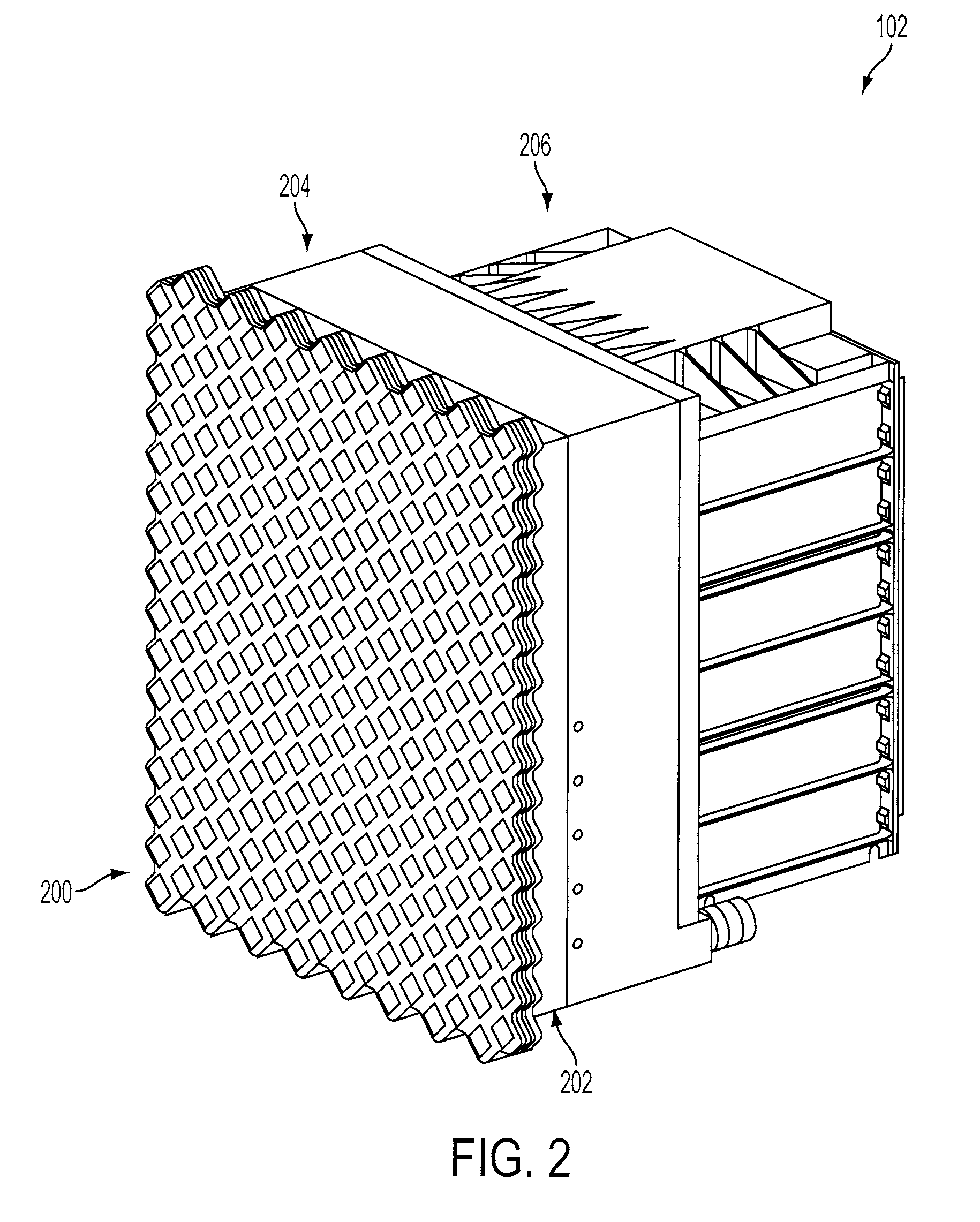
[0019]FIG. 1 shows a novel antenna assembly 20 according to an embodiment of the present invention. In a preferred embodiment, not shown, the antenna assembly 20 may be mounted on a ship. The antenna assembly 20 includes a steel front structure 106 that provides a system of walkways 502 and, optionally, bulkheads 500 which allow technicians to access various parts of the array. This embodiment of an antenna assembly 20 also includes an aluminum structural grid 104 is attached to the front structure 106. The structural grid 104 is a system of beam members 300 and 302 forming an array of rectangles. Each rectangle is sized to fit an antenna subassembly 102. The antenna subassemblies 102 have a forward housing, made up of both a lower forward housing 202 and an upper forward housing 204. An aft housing 206 is attached to the rear of the upper forward housing 204. A patch radiator 200 is secured to the front of the lower forward housing 202. A radome 100 is attached to the face of an an...


PUM


Abstract

A structural grid is provided with continuous and discontinuous beam members coupled by splices, a front structure coupled to the structural grid, the front structure including a walkway and cables, a radome coupled to the front structure. The structural grid is coupled to a plurality of antenna subassemblies. The antenna subassemblies have a forward housing including an RF manifold coupled to a circulator, an aft housing coupled to the forward housing, containing a line replaceable unit that is serviceable or maintainable through the aft housing.

Description

BACKGROUND OF THE INVENTION[0001]1. Technical Field[0002]The present invention relates to an antenna array or assembly of arrays. More particularly, the present invention relates to modular, active phased antenna arrays.[0003]2. Description of the Background Art[0004]A phased array includes an array of radiating elements, or radiators, whose signals are controlled by a beamformer to produce an antenna beam pattern that may be steered, or scanned, in different directions. Phased array technology was originally developed for unidirectional, receive-only applications, such as radio astronomy, and then extended to bidirectional, transmit and receive applications, such as radar.[0005]In a passive phased array, each radiator is coupled to a passive antenna module. For example, a passive electronically scanned array (PESA) is a bidirectional, passive phased array in which a radio frequency (RF) source provides a constant-phase, high-power transmit (Tx) signal to each passive antenna (or ph...

Claims


Application Information

Patent Timeline
Patent Type & Authority Applications(United States)
IPC IPC(8): H01Q1/42
CPCH01Q21/065H01Q21/0025
Inventor TAM, JASONDICKSTEIN, JEFF JOSEPHHEITZMANN, LAWRENCE RONALDMEEKINS, ANDREW DONALDDUMESH, MICHAEL ALEKSANDROVICHANDERSON, DANIEL DAVIDESSMAN, STEPHEN JAMESHAHN, MICHAEL ANTHONYBALDACCI, DAVE
Owner NORTHROP GRUMMAN SYST CORP
Why Eureka
Eureka Blog
Learn More