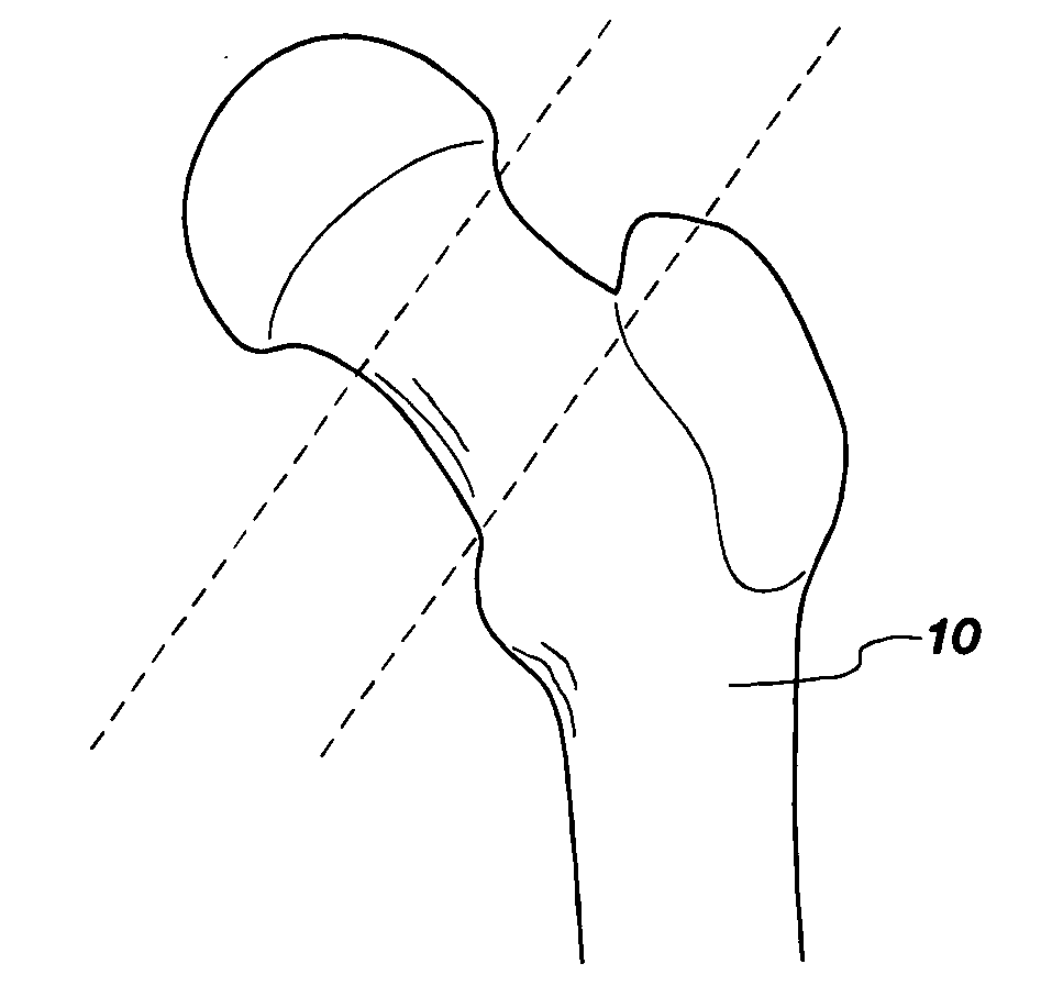
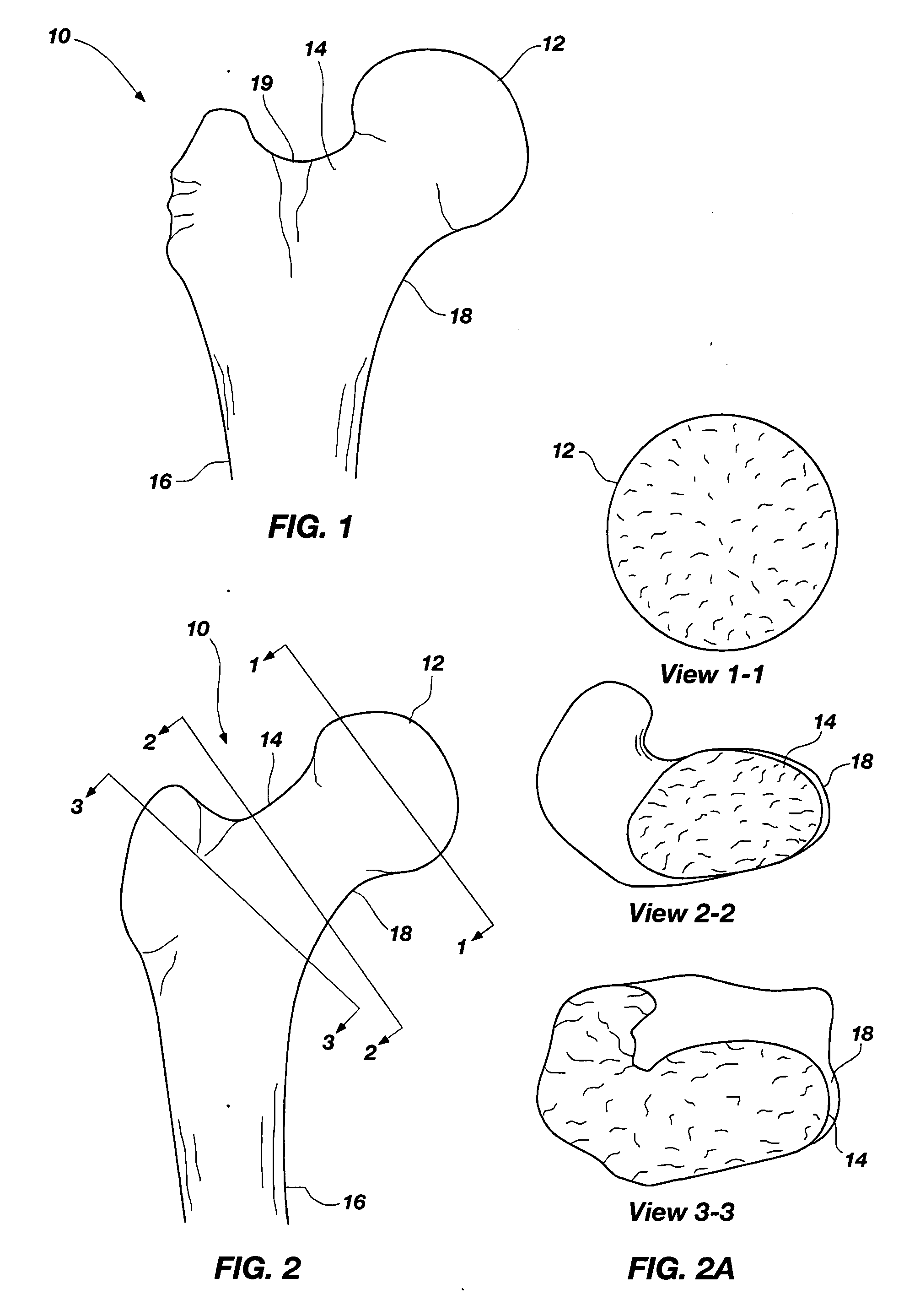
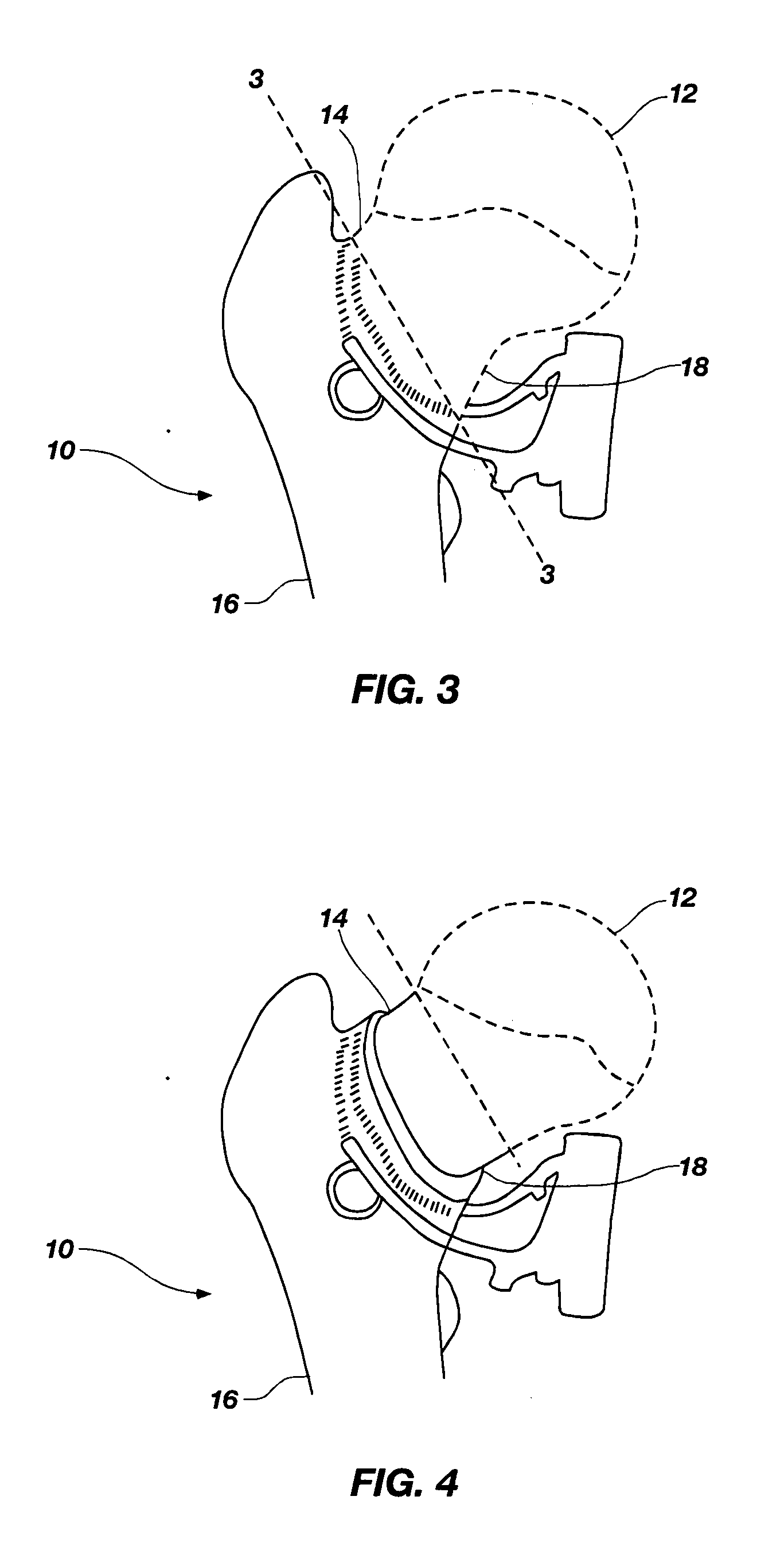
Tissue sparing implant

a tissue-sparing, total hip implant technology, applied in the field of orthopaedic implants, can solve the problems of neck sparing implants and devices on the market that have traditionally had difficulty in properly loading the bone and particularly the medial calcar portion of the femur, and the aseptic loosening failure of the implant, etc., to achieve the full potential of the neck sparing device for tha surgery

Inactive Publication Date: 2008-08-21
CONCEPT DESIGN & DEV
View PDF72 Cites 34 Cited by
  • Summary
  • Abstract
  • Description
  • Claims
  • Application Information

AI Technical Summary

Problems solved by technology

Further, if a bone is improperly loaded, then the bone will resorb, thereby providing aseptic loosening and failure of the implant.
For example, neck sparing implants and devices on the market have...

Method used


Image

  • Tissue sparing implant
  • Tissue sparing implant
  • Tissue sparing implant

Examples


Embodiment Construction

[0060]For the purposes of promoting an understanding of the principles in accordance with the disclosure, reference will now be made to the embodiments illustrated in the drawings and specific language will be used to describe the same. It will nevertheless be understood that no limitation of the scope of the disclosure is thereby intended. Any alterations and further modifications of the inventive features illustrated herein, and any additional applications of the principles of the disclosure as illustrated herein, which would normally occur to one skilled in the relevant art and having possession of this disclosure, are to be considered within the scope of the disclosure claimed.

[0061]It is to be understood that this disclosure is not limited to the particular configurations, process steps, and materials disclosed herein as such configurations, process steps, and materials may vary somewhat. It is also to be understood that the terminology employed herein is used for the purpose o...


PUM


Abstract

A femoral component of a hip implant is disclosed. The femoral component may be used specifically in a neck sparing resection (i.e., any process or device that avoids removing the femoral neck) and may include a shortened stem (with respect to a conventional stem) having a terminal flare portion for internally contacting a medial calcar portion of the proximal femur, and a significant curvature on its medial side. Other features of the femoral component include, flat side portions on the anterior and posterior sides of the stem, a lateral fin or a wing or T-back to aid in resisting torsional forces. The femoral component may also include a sagittal slot for proper fitting and placement in the femoral canal. The femoral component may also include a neck component that is modular with respect to the stem component. A head component, whether monoblock or modular with respect to the neck component, may also be utilized as part of the femoral component.

Description

CROSS-REFERENCE TO RELATED APPLICATIONS[0001]This application claims the benefit of U.S. Provisional Application No. 60 / 901,846, filed Feb. 16, 2007, entitled TISSUE SPARING IMPLANT, and this application also claims the benefit of U.S. Provisional Application No. 60 / 922,134, filed Apr. 6, 2007, entitled TISSUE SPARING IMPLANT, which are both hereby incorporated by this reference herein in their entireties, including but not limited to those portions that specifically appear hereinafter, the incorporation by reference being made with the following exception: In the event that any portion of the above-referenced provisional applications is inconsistent with this application, this application supercedes said portion of said above-referenced provisional applications.STATEMENT REGARDING FEDERALLY SPONSORED RESEARCH OR DEVELOPMENT[0002]Not Applicable.BACKGROUND[0003]1. The Field of the Invention[0004]The present disclosure relates generally to an orthopedic implant for use in a Primary To...

Claims


Application Information

Patent Timeline
IPC IPC(8): A61F2/36
CPCA61F2/36A61F2250/006A61F2/3609A61F2/3662A61F2002/30112A61F2002/30138A61F2002/30153A61F2002/30172A61F2002/30205A61F2002/30334A61F2002/30341A61F2002/30538A61F2002/30598A61F2002/30604A61F2002/30616A61F2002/30879A61F2002/3619A61F2002/365A61F2002/3652A61F2002/3656A61F2002/3668A61F2002/3686A61F2002/3696A61F2220/0033A61F2230/0004A61F2230/0017A61F2230/0019A61F2230/0052A61F2230/0067A61F2250/0006A61F2/367A61F2/3601A61F2002/30339A61F2002/30594A61F2002/3054A61F2002/30593A61F2002/30884
Inventor MCTIGHE, TIMOTHYHENRY, JIMBANKS, STEVERIBOT, MICHAEL
Owner CONCEPT DESIGN & DEV
Why Eureka
Try Eureka