
Point to multipoint device for communication with a plurality of telecommunications units

a multi-point device and communication technology, applied in the field of point to multi-point devices, can solve the problems of reducing the overall system throughput, reducing the number of resources (i.e. channels) in the wireless network, and degrading the quality of the received signal, so as to reduce the average cci, the average cci is observed, and the beam switching can occur quickly.

Active Publication Date: 2008-08-21
AIRSPAN COMM +1
View PDF12 Cites 35 Cited by
  • Summary
  • Abstract
  • Description
  • Claims
  • Application Information

AI Technical Summary

Benefits of technology

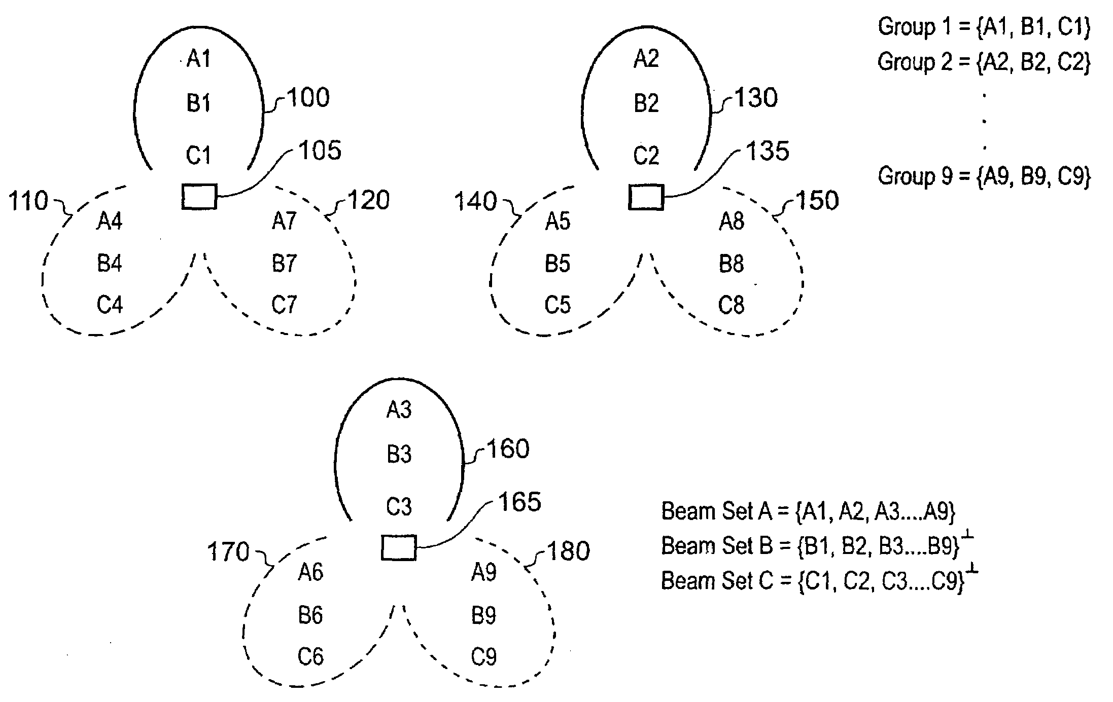
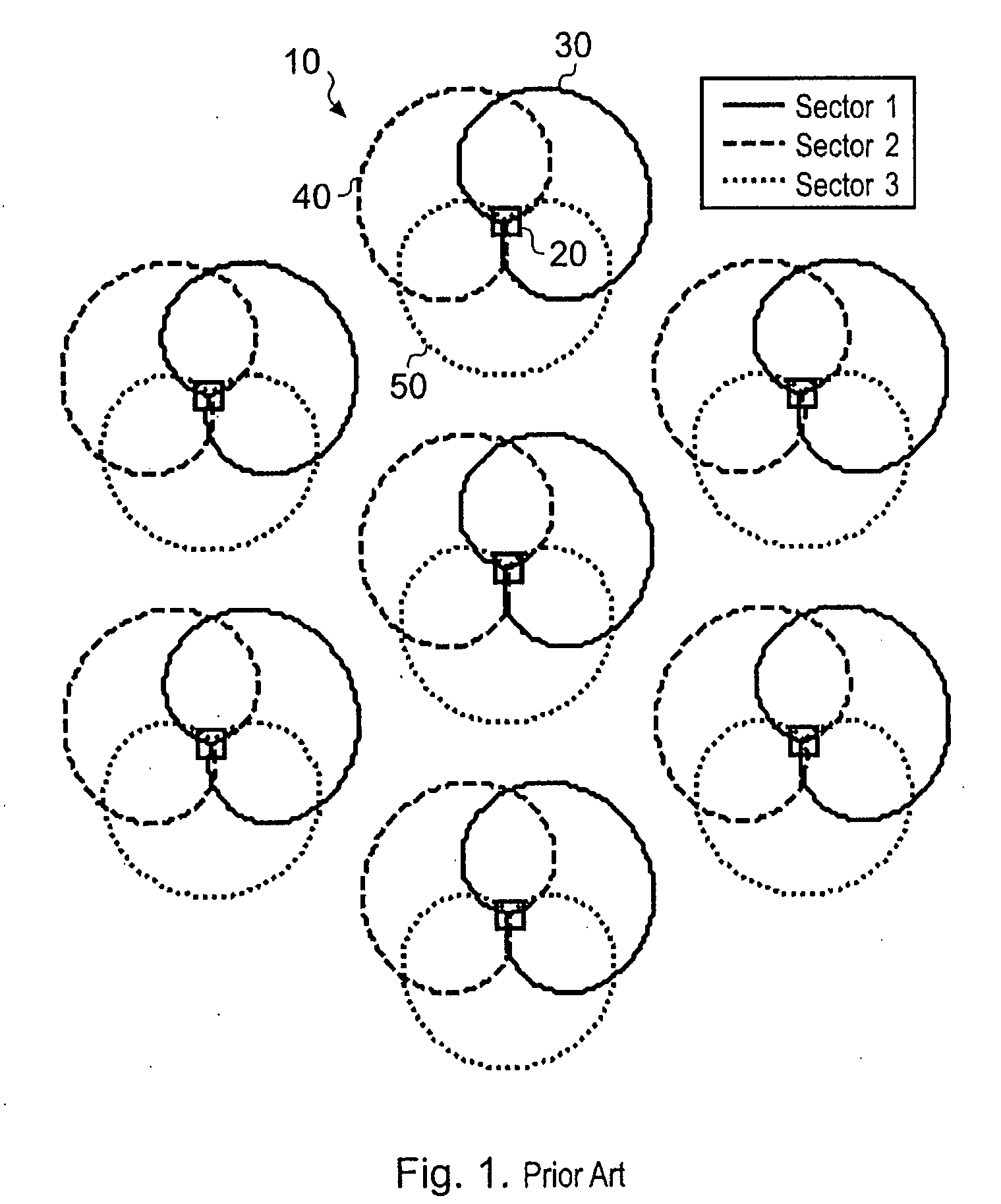
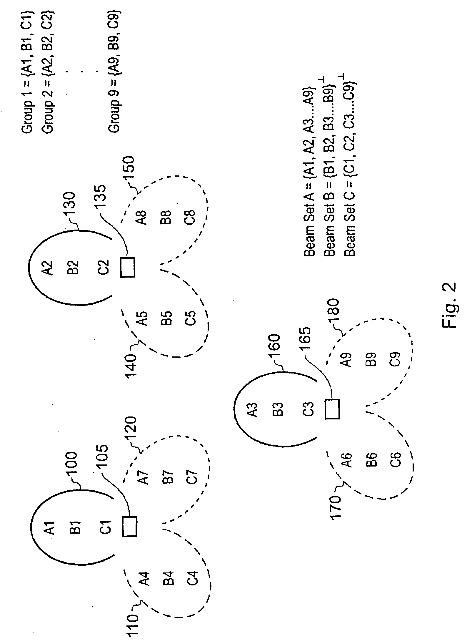
[0027]Additionally, in accordance with the present invention, it has been found that by arranging that each beam within each set is generated randomly with respect to other beams in that set, this results in a lower average CCI observed within the wireless network. By generating the beams within a set randomly with respect to each other, this typically results in the beams being used at any point in time having quite different beam shapes. When considering the wireless network as a whole, it is often the case that each cell is sectorised in the same way. When adopting the design of point to multipoint device of the present invention in each such cell, this means that the beams used for corresponding sectors in each cell at any point in time will typically have different shapes when compared with each other, and will also have different directions of propagation when compared with each other. These different shape and directional properties of the beams result from the random generation employed by the beam set generation logic and have been found to give rise to the lowering of the average CCI observed within the wireless network when compared with conventional systems where the beams are not randomly generated.
[0028]Further, since the switch times are synchronised across the wireless network, beam switching can occur quickly, and as a result multi-user diversity can be exploited by seeking to transmit to telecommunications units having the best channel quality.
[0036]In one embodiment, once the multiple sets of beams have been generated by the beam set generation logic, they are not changed. However, in an alternative embodiment, the beam set generation logic is operable, on occurrence of one or more predetermined events, to re-perform generation of the multiple sets of beams, thereby facilitating an evening of the quality of service provided to each telecommunications unit over time. Since each time the generation of the multiple sets of beams is re-performed, this will result in another random generation of each beam within each set, then this process will result in random changes in the shape of the beams used, and their predominant direction of propagation, and as a result this will produce an evening of the quality of service provided to each telecommunications unit over time.
[0038]The one or more predetermined events that are used to trigger the re-performance of the generation of the multiple sets of beams can take a variety of forms. However, in one embodiment, the one or more predetermined events comprise at least an elapsing of a predetermined time interval, the predetermined time interval being larger than the period between switch times calculated by the beam switching logic. Indeed, it will typically be the case that the predetermined time interval is significantly larger than the period between switch times calculated by the beam switching logic, so as to allow the sets of beams generated by the beam set generation logic to be used for a significant period of time before a replacement sets of beams is generated, thereby reducing any impact on performance resulting from re-assigning the telecommunications units to appropriate beams.

Problems solved by technology

Whilst such a scheme is necessary to maintain an acceptable QoS, data repetition has the drawback of reducing the overall system throughput.
The total number of resources (i.e. channels) in a wireless network is limited.
CCI degrades the quality of the received signal and thus CCI impacts negatively on the system throughput.
Typically, such steered beam systems are more complex to design than fixed multi-beam systems.
There is an inherent delay between the time instance when a particular MCS is requested by an SS and the time instance when that SS is scheduled.
As a result, the requested MCS was too pessimistic.
The requested MCS is in that case too optimistic, and the requested MCS may not be sufficiently robust enough to guarantee the desired QoS.
This latter outcome is more dramatic, since many retransmissions will occur resulting in severe system throughput degradation.
Due to the complexity of design of steered beam systems, and the almost infinite variations in CCI levels that can result from the use of such steered beam systems, most systems employing smart antenna arrays for downlink communication have been based on fixed multi-beam systems.
Hence, if M simultaneous beams are used, then the received energy at the mobile will be reduced by M. Whilst this alleviates abrupt time varying changes in the CCI it gives rise to an elevated CCI level at all times, which impacts negatively on the system throughput.
A problem with the above-described approach is that for a few milliseconds after a beam switch, there are transient periods where the CCI will fluctuate rapidly.
Another drawback with slow switched beam systems is that multi-user diversity is not fully exploited.
In the above-described system only parts of a sector are illuminated by a beam, and hence there may be users in other parts of the sector that experience constructive fading with signal quality that exceeds that of the signal quality of the scheduled user, but which cannot be scheduled in preference to that user due to not being illuminated by the beam in use at the time.
However, when using a slow switched beam system, it is not possible to make best use of the multi-user diversity.
Another problem with slow switched beam systems is the increase in latency resulting from the time taken to switch the beams, which can have an adverse effect on the QoS.
Managing and updating the maps is a cumbersome, memory intensive task.
Another disadvantage of the scheme proposed in US 2004 / 0235527 (and indeed of the earlier mentioned prior art techniques) is that the multiple antenna beam base stations described therein require calibrated arrays, which comprise of calibration units that estimate and correct any amplitude and phase distortions present in the transmit and / or receiver chain from the antenna elements down to baseband processing in the base station.
Antenna architectures of this type are expensive to produce.

Method used


Image

  • Point to multipoint device for communication with a plurality of telecommunications units
  • Point to multipoint device for communication with a plurality of telecommunications units
  • Point to multipoint device for communication with a plurality of telecommunications units

Examples


example

[0083]Let the number of antennas N=3 and the number of beams B=3. Let the random matrix A be given by

A=[-0.4521-0.9715i1.4041-1.2118i-1.2413+1.4178i-2.0185+1.0302i0.3496-1.2731i0.2494+1.3642i1.6444-0.4617i0.1980+2.1392i-0.8949-0.0644i]

SVD returns the unitary matrix U, which is given by

U=[-0.3763-0.4220i0.3891+0.4194i0.5022-0.3175i-0.5802+0.1239i-0.1419+0.5469i-0.4667+0.3333i0.5157-0.2498i0.4954+0.3287i-0.5528-0.1121i]

[0084]Thus, on frame number one the beam vector weight u1 would be used. On frame number 2 the beam vector weight u2 would be used and on frame number 3 the beam weight U3 would be used. The beam weights are given by

u1=[-0.3763-0.4220i-0.5802+0.1239i0.5157-0.2498i]u2=[0.3891+0.4194i-0.1419+0.5469i0.4954+0.3287i]u3=[0.5022-0.3175i-0.4667+0.3333i-0.5528-0.1121i]

[0085]For example on frame number 3, the data is weighted by 0.5022-0.3175i and transmitted from the first antenna. During frame number 3, the data is also weighted by −0.4667+0.3333i and transmitted from the secon...


PUM


Abstract

A point to multipoint device for use in a wireless network to provide wireless communication with a plurality of telecommunications units is described, for communication from the point to multipoint device to the telecommunications units, the point to multipoint device being operable to employ multiple sets of beams, at any point in time one set being used. The point to multipoint device comprises beam set generation logic for generating the multiple sets of beams arranged into one or more groups, each group comprising one beam from each set. Within each group the beams of that group are orthogonal with respect to each other, and each beam within each set is generated randomly with respect to other beams in that set. An interface is provided for receiving a synchronisation signal issued to all point to multipoint devices in the wireless network. Beam switching logic is then used to determine, having regard to the synchronisation signal, switch times at which the point to multipoint device switches from one set of beams to another set of beams, the switch times being the same for all point to multipoint devices in the wireless network. An antenna array is controlled by the beam switching logic to produce at any point in time one of the sets of beams for transmitting data forming the communication to the telecommunications units. The use of such sets of beams has been found to lower the average co-channel interference observed within the wireless network.

Description

BACKGROUND OF THE INVENTION[0001]1. Field of the Invention[0002]The present invention relates to a point to multipoint device for use in a wireless network to provide wireless communication with a plurality of telecommunication units, to a method of operating such a device, and to a wireless network comprising a plurality of such point to multipoint devices.[0003]2. Description of the Prior Art[0004]Point to multipoint devices within a wireless network may take a variety of forms. For example, such a point to multipoint device may take the form of a relay node or repeater used to propagate data within the wireless network. Such relay nodes or repeaters typically amplify and forward or decode and forward received signals within the wireless network. Another example of a point to multipoint device would be a base station associated with a cell of the wireless network for communicating over wireless links with a number of subscriber stations and / or relay nodes in the cell.[0005]A wirel...

Claims


Application Information

Patent Timeline
Patent Type & Authority Applications(United States)
IPC IPC(8): H04Q7/00H04W16/28H04W72/08
CPCH04W16/28H04B7/0851H04B7/0617H04B7/0695H01Q3/26H04B7/08H04L1/06
Inventor LYSEJKO, MARTINLOGOTHETIS, ANDREW
Owner AIRSPAN COMM
Learn More