Medical intervention instrument

a technology of intervention wire and actuation device, which is applied in the field of medical intervention wire, can solve the problems that the intervention section disclosed in the patent document 1 is subject to unintended movement and the maneuvering wire cannot be held with a predetermined force, and achieve the effect of preventing erroneous actuation

Active Publication Date: 2008-08-14
OLYMPUS CORP
View PDF5 Cites 7 Cited by
  • Summary
  • Abstract
  • Description
  • Claims
  • Application Information

AI Technical Summary

Benefits of technology

[0013]The medical intervention instrument can maintain a certain attitude of the intervention section, necessary to be maintained, that is actuated based on displacement input by the maneuvering section since the distal direction movement inhibitor section can move the transmission section toward the proximal end of the sheath even if an external force directed to the distal end of the sheath is loaded to the transmission section, Also, a certain attitude of the intervention section can be maintained since the proximal direction movement inhibitor section can move the transmission section toward the distal end of the sheath even if an external force directed toward the proximal end of the sheath is loaded.
[0015]The medical intervention instrument, irrespective to an external force attempting to move the transmission section toward the distal end, can maintain the fixed state of the transmission section with the guide section since the first fixing section is urged by the first urging section. Alternatively, the fixed state of the transmission section with the guide section can be maintained irrespective to the transmission section attempting to move toward the proximal end since the second fixing section is urged by the second urging section. Therefore, a desirable attitude of the intervention section can be maintained even if an external force is applied in either direction.
[0021]The medical intervention instrument can prevent movement of the transmission section in the vicinity of the intervention section more desirably than in a case where movement of the transmission section based on an external force is prevented in the vicinity of the proximal end of the sheath. Therefore, it is possible to prevent erroneous actuation of the intervention section based on an external force applied to an unactuated state of the intervention section more reliably.

Problems solved by technology

However, the intervention section disclosed by Patent Document 1 is subject to unintended manner of movement if the medical intervention instrument is applied an external force that is more significant than a friction force between a locking screw and a maneuvering wire fixed by a compressing force by the locking screw.
In addition, the jaw section of the medical intervention instrument disclosed by Patent Document 2 cannot be fixed between two groove sections; therefore, the maneuvering wire cannot be held with a predetermined force.
Furthermore, separate manipulations associated with the maneuvering section, i.e., actuation of the intervention section and release of the certain attitude of the intervention section immobilize quick transition to next operation.

Method used


Image

  • Medical intervention instrument
  • Medical intervention instrument
  • Medical intervention instrument

Examples


first embodiment

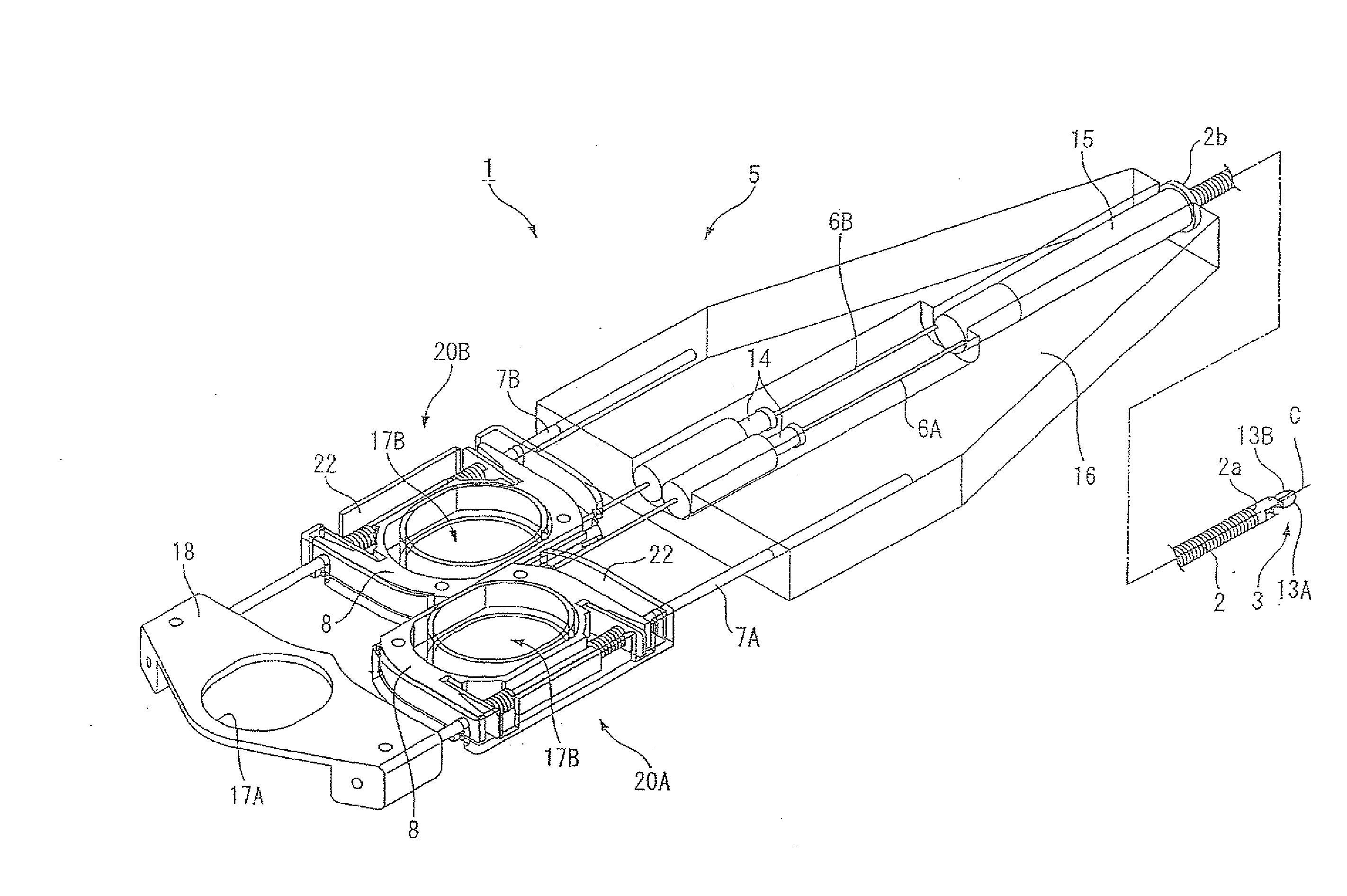
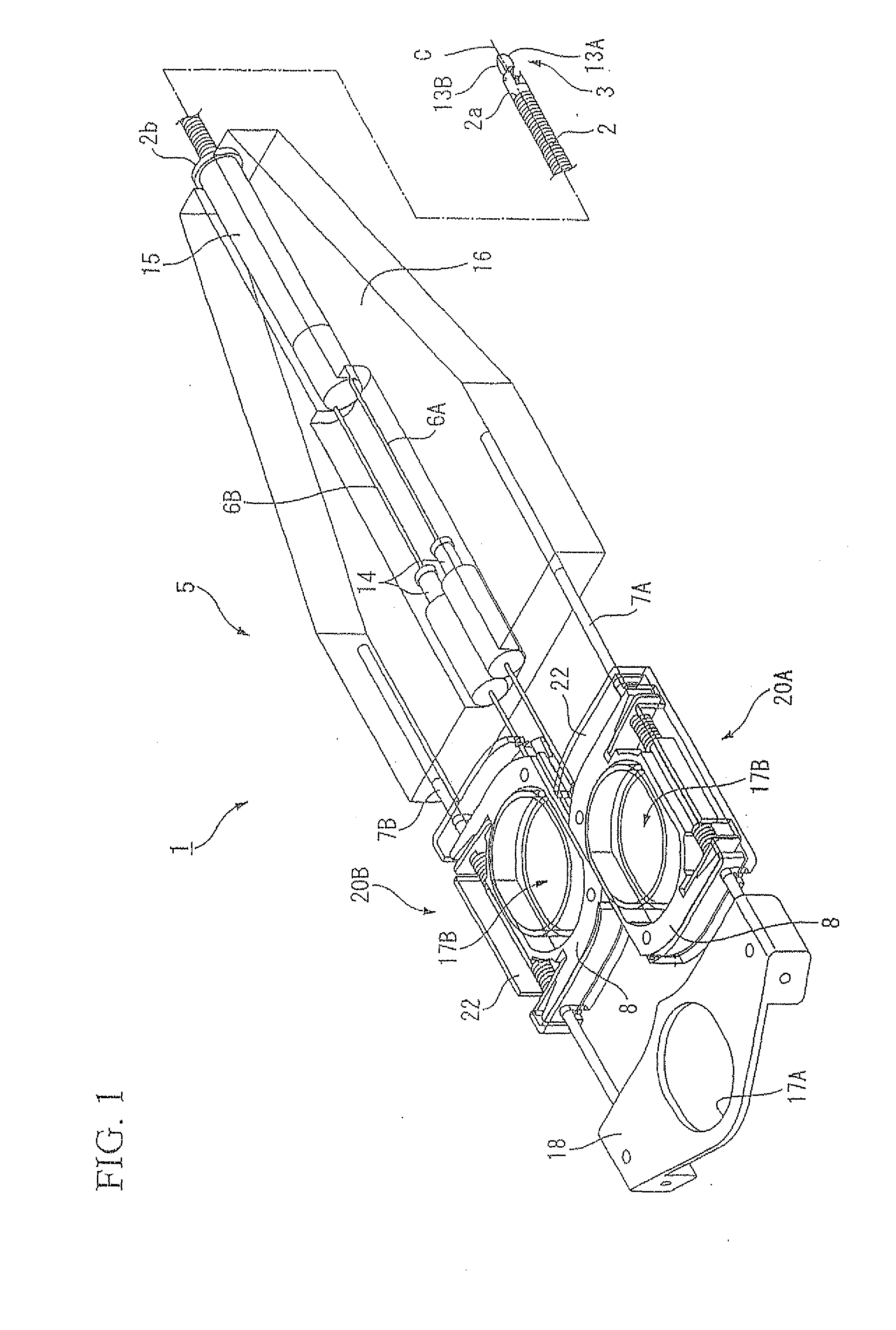
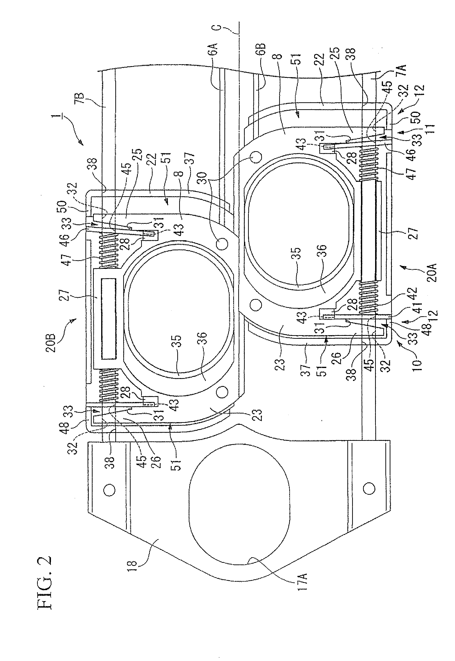
[0037]the present invention will be explained with reference to FIGS. 1 to 10.

[0038]As illustrated in FIGS. 1 to 5, a grasping forceps 1 (medical intervention instrument) according to the present embodiment is provided with: a sheath 2 extending in an axial direction and having a distal end 2a and a proximal end 2b; an intervention section 3 disposed at the distal end 2a of the sheath 2; a pair of maneuvering wires 6A and 6B that move in extending and retracting directions along an axial line C of the sheath 2 in the sheath 2; a maneuvering section 5, disposed at the proximal end 2b of the sheath 2, that accepts displacement information associated with the pair of maneuvering wires 6A and 6B relative to the sheath 2; a pair of round bar guide sections 7A and 7B that guide the maneuvering wires 6A and 6B in the axial line C of the sheath 2; a plastic extending-and-retracting member (transmission section) 8, fixed and connected to proximal ends of the maneuvering wires 6A and 6B, that...


PUM


Abstract

A grasping forceps 1 includes: a pair of guide sections 7A and 7B that guide maneuvering wires 6A and 6B in a direction of an axial line C of a sheath; an extending-and-retracting member (transmission section) 8 that transmits displacement information of the maneuvering section to the maneuvering wires 6A and 6B and outputs the displacement information to the intervention instrument; a distal direction movement inhibitor section (specific directional movement-inhibitor section) 10 that allows the sheaths of the maneuvering wires 6A and 6B toward the distal end; a proximal direction movement inhibitor section (specific directional movement-inhibitor section) 11 that allows the sheaths of the maneuvering wires 6A and 6B toward the distal end; and an locked-state-releasing section 12 that releases an engaging state of the guide sections 7A and 7B with the distal direction movement inhibitor section 10 or the proximal direction movement inhibitor section 11 based on the displacement input by the maneuvering section. Accordingly, an medical intervention instrument can be provided that can maintain a certain attitude of the intervention instrument once established during intervention even if an external force is applied, and that can carry out identical operations simultaneously, i.e., manipulating of the intervention instrument and releasing of a certain attitude of the intervention instrument.

Description

BACKGROUND OF THE INVENTION[0001]1. Field of the Invention[0002]The present invention relates to a medical intervention instrument for use in interventions including surgical or arthroscopic operation.[0003]The present application is based on PCT application No. PCT / JP2006 / 315829, filed Aug. 10, 2006, in Japan, the content of which is incorporated herein by reference.[0004]2. Description of the Related Art[0005]Various holding mechanisms have been proposed to maintain a certain attitude of an intervention section during an intervention carried out with a medical intervention instrument that manipulates an intervention section connected to the distal end of an elongated sheath with a maneuvering section connected to the proximal end of the sheath. (See, for example, Patent Documents 1 and 2)[0006]The medical intervention instrument disclosed by Patent Document 1 is provided with screws that are adjustable to press a maneuvering wire onto a maneuvering section and limit movement of th...

Claims


Application Information

Patent Timeline
Patent Type & Authority Applications(United States)
IPC IPC(8): A61B17/00
CPCA61B10/06A61B17/29A61B19/30A61B2017/2946A61B2017/2911A61B2017/2912A61B2017/2939A61B2017/2845A61B90/03
Inventor HASHIMOTO, TATSUTOSHI
Owner OLYMPUS CORP
Why Eureka
Try Eureka