
Joint for Plumbing

a technology for plumbing joints and joints, applied in the direction of hose connections, couplings, pipe couplings, etc., can solve the problems of inconvenient screwing and unscrewing in a small place, inconvenient installation of hoses, and the inability to meet the needs of piping, so as to maximize the tensile stopping power of the joint, increase the pressed rate and sealability, and facilitate the effect of insertion

Inactive Publication Date: 2008-08-14
WITHUS
View PDF11 Cites 8 Cited by
  • Summary
  • Abstract
  • Description
  • Claims
  • Application Information

AI Technical Summary

Benefits of technology

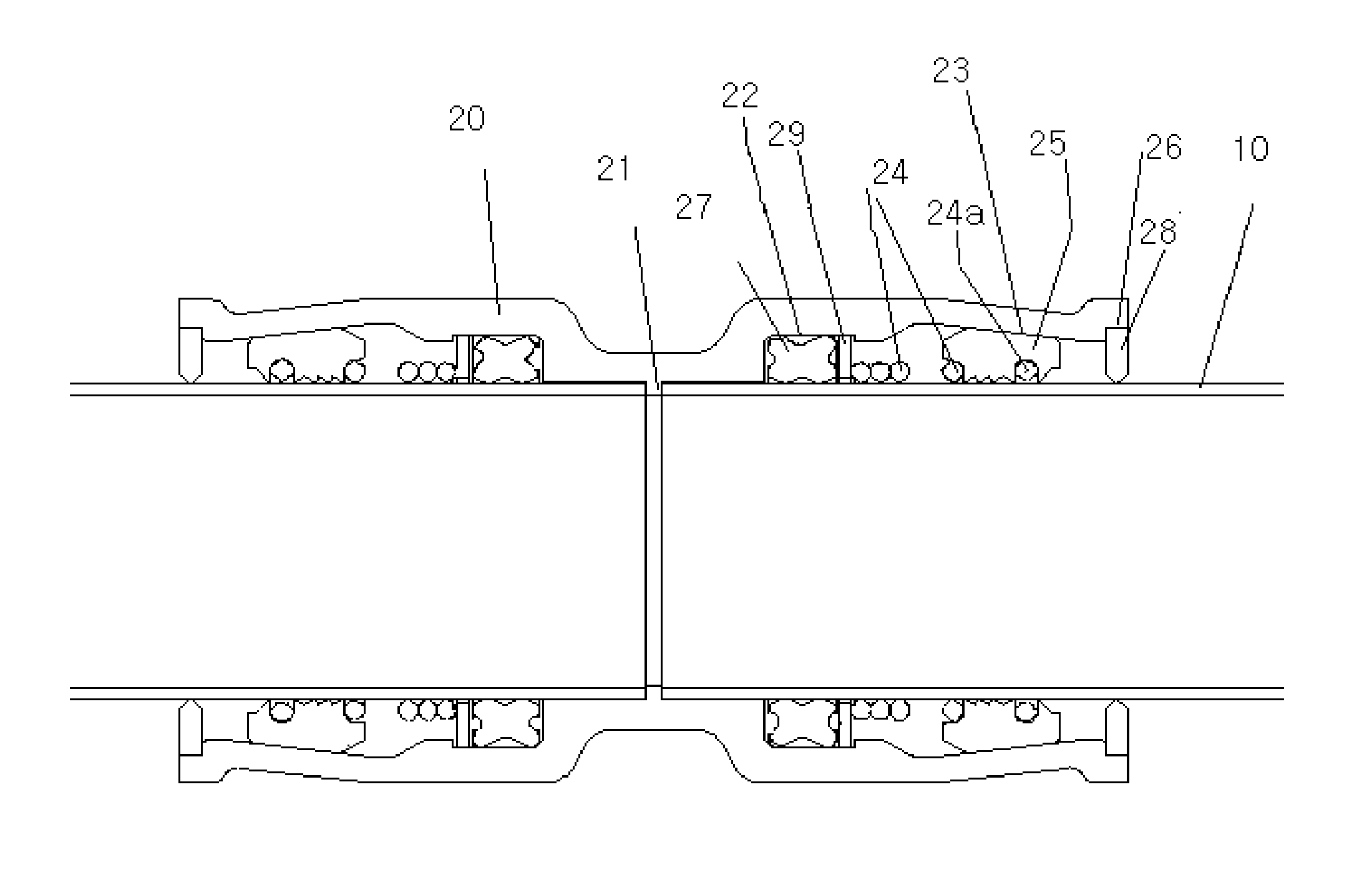
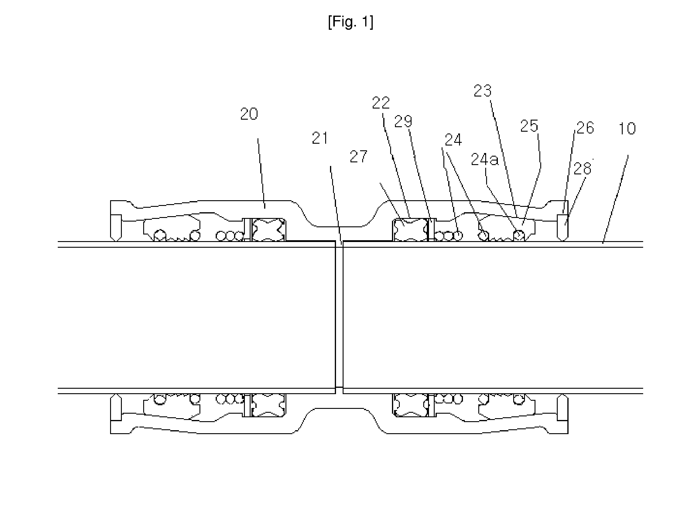
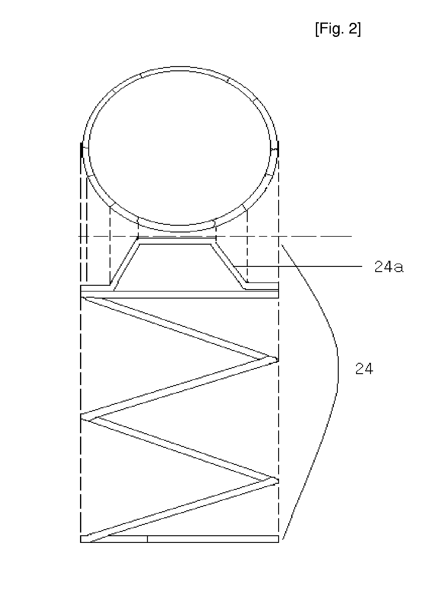
[0014]Since the final round of the spring of the conventional joint is in the trapezoidal shape, it is complicated to produce the spring, and it is difficult to maximize the pipe contact surface of the stopper. However, the spring according to the present invention allows the stopper of a wide area to be inserted into the joint, thereby maximizing tensile stopping power of the joint.
[0015]The present invention increases the pressed rate and sealability and allows the pipe to be easily inserted therein by adopting the X-ring.
[0016]By mounting the dust seal in the inlet, the present invention can prevent introduction of dust or sewage, so as to extend lifetime of the product. Furthermore, the present invention does not require additional cap as the pipe is sealed the moment the pipe is inserted, when the pipe is buried under the ground.

Problems solved by technology

In general, a joint using screw coupling can provide a secure and permanent piping, but has several problems in that it is inconvenient to screw and unscrew in a small place, and in that lots of time and manpower are required for piping.
However, the conventional wedge type joint 10 is not great in tensile stopping power of a product because a contact surface between the stopper and the surface of the pipe is not maximized.
In the above case, when the compressed rate of the packing is large, the joint provides an excellent sealability but it is difficult to insert the pipe.
On the contrary, when the compressed rate is small, the pipe can be easily inserted, but sealability is deteriorated.

Method used


Image

  • Joint for Plumbing
  • Joint for Plumbing
  • Joint for Plumbing

Examples


Embodiment Construction

[0023]The present invention will now be described in detail in connection with preferred embodiments with reference to the accompanying drawings.

[0024]The present invention relates to a wedge type joint for inserting and fixing a pipe into two bodies of a connector.

[0025]The wedge type joint has a body 20 having a symmetrical form from the center, and the body 20 includes: stopping parts 21 formed at both sides from the center of the body 20 and having the diameter identical with the inner diameter of a pipe 10 to be inserted into the body 20; extended parts respectively extending from the stopping parts 21 to a predetermined limit of the body 20 for closely contacting and supporting the pipe 10; concave parts 22, each being formed from the extended part to a pre-determined limit toward an inlet 26; tapered parts 23, each having a diameter greater than that of the concave part 22 and gradually narrowed toward the inlet 26; and inlets 26, each being formed in such a manner as to be b...


PUM


Abstract

The present invention relates to a joint for plumbing using a wedge action, which can easily and rapidly assemble and disassemble a pipe. The joint can maximize tensile stopping power of the product by mounting a stopper in such a manner as to occupy the maximum area, increase sealing effect and convenience in insertion of the pipe by adopting a packing the most suitable for the joint, and prevent introduction of dust from the outside. For this, a spring is designed in such a way that the final round of the spring forms a round, and thereby the present invention maximizes a stopper receiving capacity. In addition, the present invention adopts an X-ring as a packing, and a dust seal is mounted in an inlet in which the pipe is inserted.

Description

TECHNICAL FIELD[0001]The present invention relates to a joint for plumbing using a wedge action, which can easily and rapidly assemble and disassemble a pipe, maximize tensile stopping power of the product by mounting a stopper in such a manner as to occupy the maximum area, increase sealing effect and convenience in insertion of the pipe by adopting a packing the most suitable for the joint, and prevent introduction of dust for the outside.BACKGROUND ART[0002]In general, a joint using screw coupling can provide a secure and permanent piping, but has several problems in that it is inconvenient to screw and unscrew in a small place, and in that lots of time and manpower are required for piping.[0003]To solve the above problems, a joint for plumbing using a wedge principle (hereinafter, referred to as a wedge type joint. The wedge type joint can complete coupling by inserting a pipe into the joint without any screw structure and deformation of the pipe. A conventional wedge type joint...

Claims


Application Information

Patent Timeline
Patent Type & Authority Applications(United States)
IPC IPC(8): F16L21/02F16L17/00F16L21/00F16L21/03F16L21/08
CPCF16L2201/80F16L37/0925F16J15/02F16L21/007F16L21/02
Inventor KIM, SUK-YOON
Owner WITHUS
Learn More