
Method and apparatus for removing ice from outdoor housing for an environmental conditioning unit

a technology for environmental conditioning and outdoor housing, applied in the field of environmental conditioning systems, can solve the problems of reducing the efficiency and effectiveness of the environmental conditioning system, reducing the air flow available,

Inactive Publication Date: 2008-08-14
LENNOX MFG
View PDF14 Cites 32 Cited by
  • Summary
  • Abstract
  • Description
  • Claims
  • Application Information

AI Technical Summary

Benefits of technology

"The present invention provides a method and apparatus for removing ice from an outdoor housing for an environmental conditioning unit. The method involves operating the fan of the conditioning unit at different speeds and directions to move air past the coil structure for heating or cooling the unit. The apparatus includes a control unit and sensor units to effect the operation of the fan based on predetermined operating parameters. The technical effects of the invention include improving the efficiency and reliability of the conditioning unit by preventing ice buildup on the coil structure and reducing energy consumption during the defrost mode."

Problems solved by technology

Such icing over reduces air flow available for drawing over the outside coil and reduces efficiency and effectiveness of the environmental conditioning system.

Method used


Image

  • Method and apparatus for removing ice from outdoor housing for an environmental conditioning unit
  • Method and apparatus for removing ice from outdoor housing for an environmental conditioning unit
  • Method and apparatus for removing ice from outdoor housing for an environmental conditioning unit

Examples


Embodiment Construction

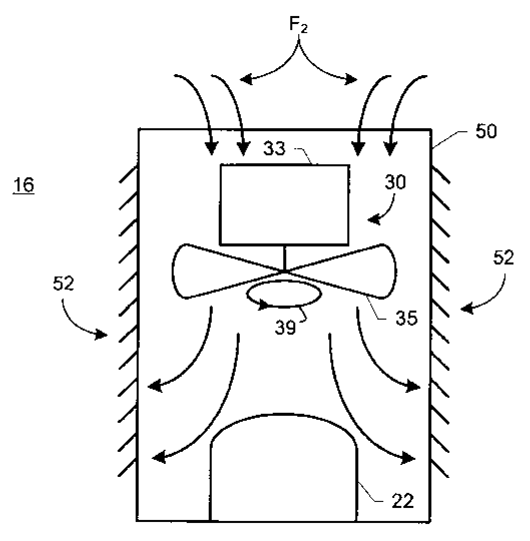
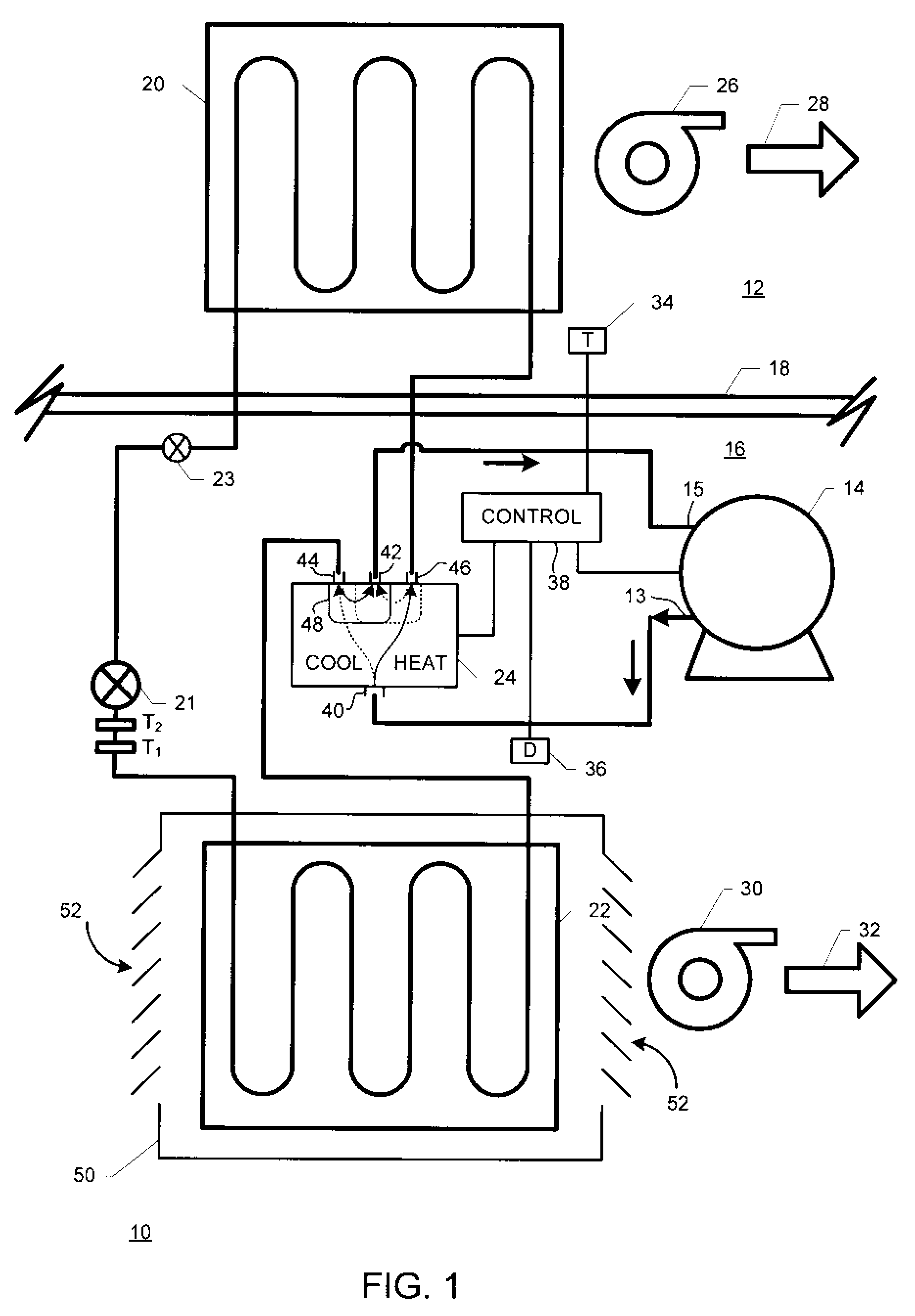
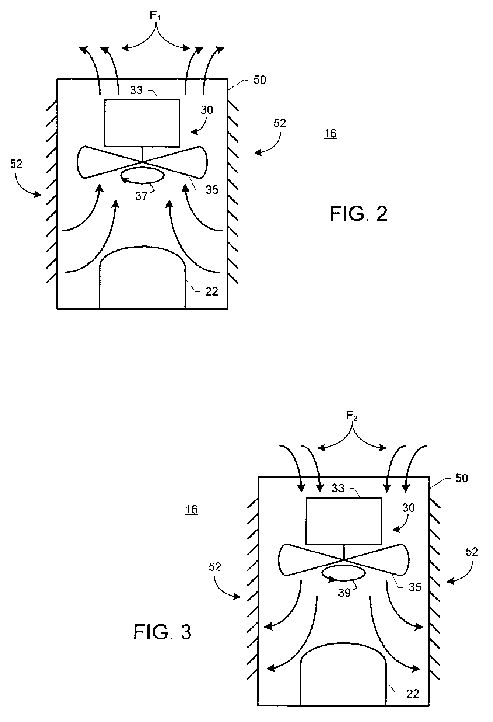
[0015]FIG. 1 is a schematic diagram of a heat pump environmental conditioning system. In FIG. 1, a heat pump system 10 is installed for conditioning an interior or inside space 12. A compressor 14 is situated in an exterior or outside space 16 outside a wall 18. An interior or inside coil 20 is situated in interior space 12. Interior coil 20 is in fluid communication with an exterior or outside coil 22 and with compressor 14 in a fluid network involving a reversing valve 24, an expansion valve 21 and an expansion valve 23. Exterior coil 22 and reversing valve 24 are situated in exterior space 16. A blower unit 26 urges air across interior coil 20 in a direction indicated by an arrow 28. A blower unit 30 urges air across exterior coil 22 in a direction indicated by an arrow 32. Exterior coil 22 may be substantially enclosed within a housing 50. Housing 50 may include louvers 52 or other access structures for permitting air flow from outside space 16 about exterior coil 22 in response...


PUM


Abstract

A method for removing ice from an outdoor housing for an environmental conditioning unit that includes the housing surrounding a coil and a fan for moving air past the coil includes the steps of: (a) operating the fan at a first speed in a first direction to move air in a first flow past the coil while the conditioning unit is in a heating mode; (b) disengaging the fan when the conditioning unit is in a defrost mode; (c) operating the fan at a second speed in a second direction to move air in a second flow past the coil when an operational parameter attains a first value; and (d) operating the fan in the first direction at the first speed to move air in the first flow when the operational parameter attains a second value.

Description

BACKGROUND OF THE INVENTION[0001]The present invention is directed to environmental conditioning systems, and especially to environmental conditioning systems employing heat pump technology and operated in cold environments tending to ice up outdoor units of the systems.[0002]Environmental conditioning systems, such as heat pump systems, typically include indoor components arranged within a space to be conditioned and outdoor components situated outside the space to be conditioned. Environmental conditioning in the context of this description includes air conditioning of an interior space, such as heating and cooling of the interior space.[0003]In cold climate areas, housing structures, such as louvered housings, surrounding an outside coil of an environmental conditioning system may become iced over. Such icing over reduces air flow available for drawing over the outside coil and reduces efficiency and effectiveness of the environmental conditioning system.[0004]There is a need for...

Claims


Application Information

Patent Timeline
Patent Type & Authority Applications(United States)
IPC IPC(8): F25B13/00F25D21/00
CPCF24F1/48F24F1/50F24F13/22F24F2011/0089F25D2323/00283F25B2313/02741F25B2313/0294F25D21/002F25B13/00F24F11/42
Inventor GIALLOMBARDO, RICHARDKEOPPEL, KEVINBERG, ERICBUCKLEY, PAULDENBOER, PETER
Owner LENNOX MFG
Learn More