
Gasifier liner

Active Publication Date: 2008-08-07
GAS TECH INST
View PDF21 Cites 36 Cited by
  • Summary
  • Abstract
  • Description
  • Claims
  • Application Information

AI Technical Summary

Problems solved by technology

An issue with existing gasification technologies is that they generally have high capital costs and / or relatively low availability.
One cause of low availability is complex or short-lived gasifier liner designs.
While membrane liners have a longer life than refractory liners, the complexity of the liner can increase the cost of the gasifier up to 2 to 3 times.
While regeneratively cooled liners provide significant benefits in gasification technology when compared to refractory liners and membrane liners, one of the technical challenges of using regeneratively cooled liners is managing the thermal growth of the liner.
Thus, as the temperature inside the gasifier increases, the rates of thermal expansion of the ceramic liner and the metal backing structure are mismatched.
Another challenge with regard to regeneratively cooled liners is the specific implementation of the metal / ceramic joining required to establish a closed-loop (regenerative) cooling circuit.
In addition, there is a risk that a small crack in the liner could alter the performance and efficiency of the gasifier, eliminating the ability to co-generate power.

Method used


Image

  • Gasifier liner
  • Gasifier liner
  • Gasifier liner

Examples


first embodiment

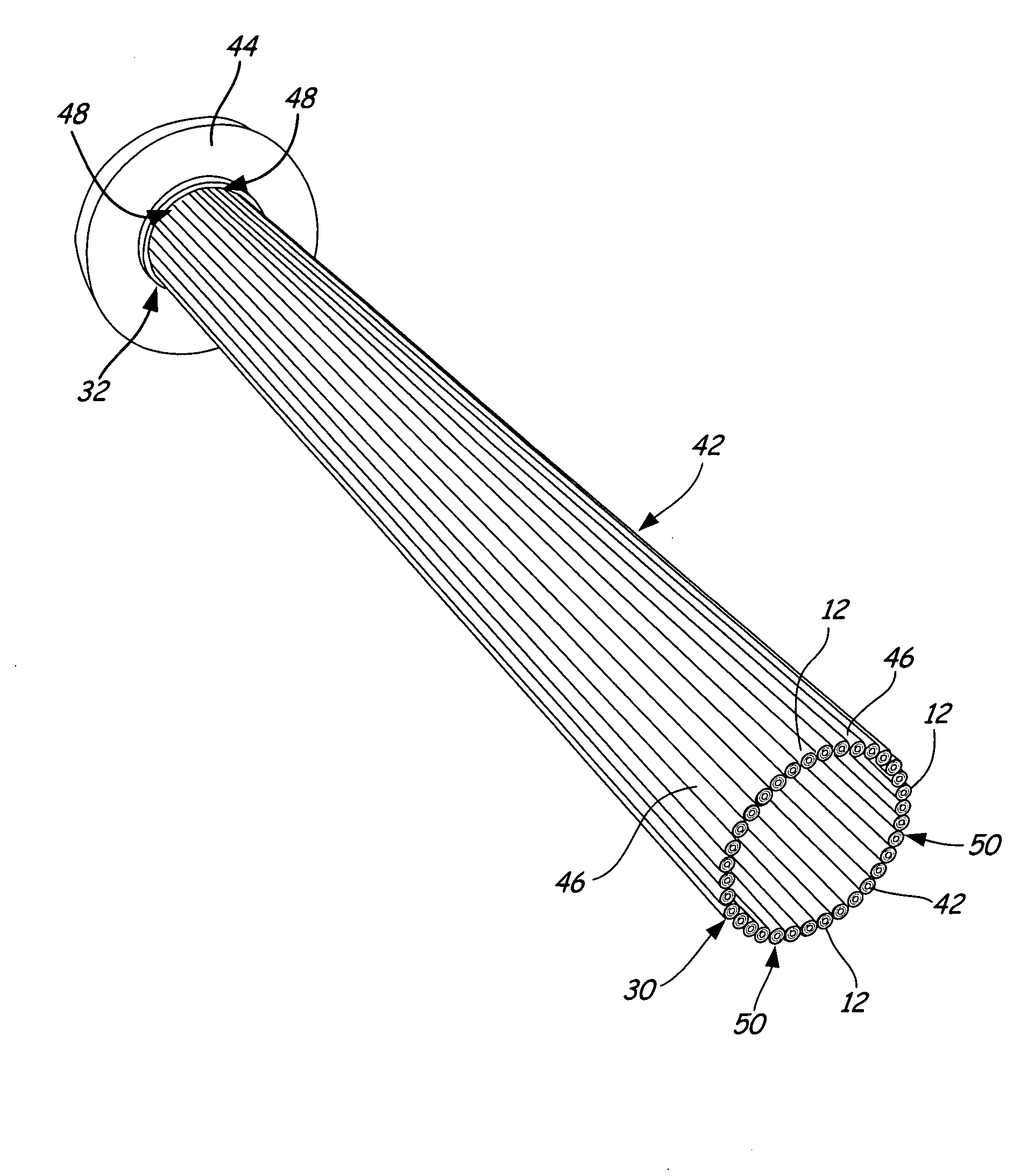
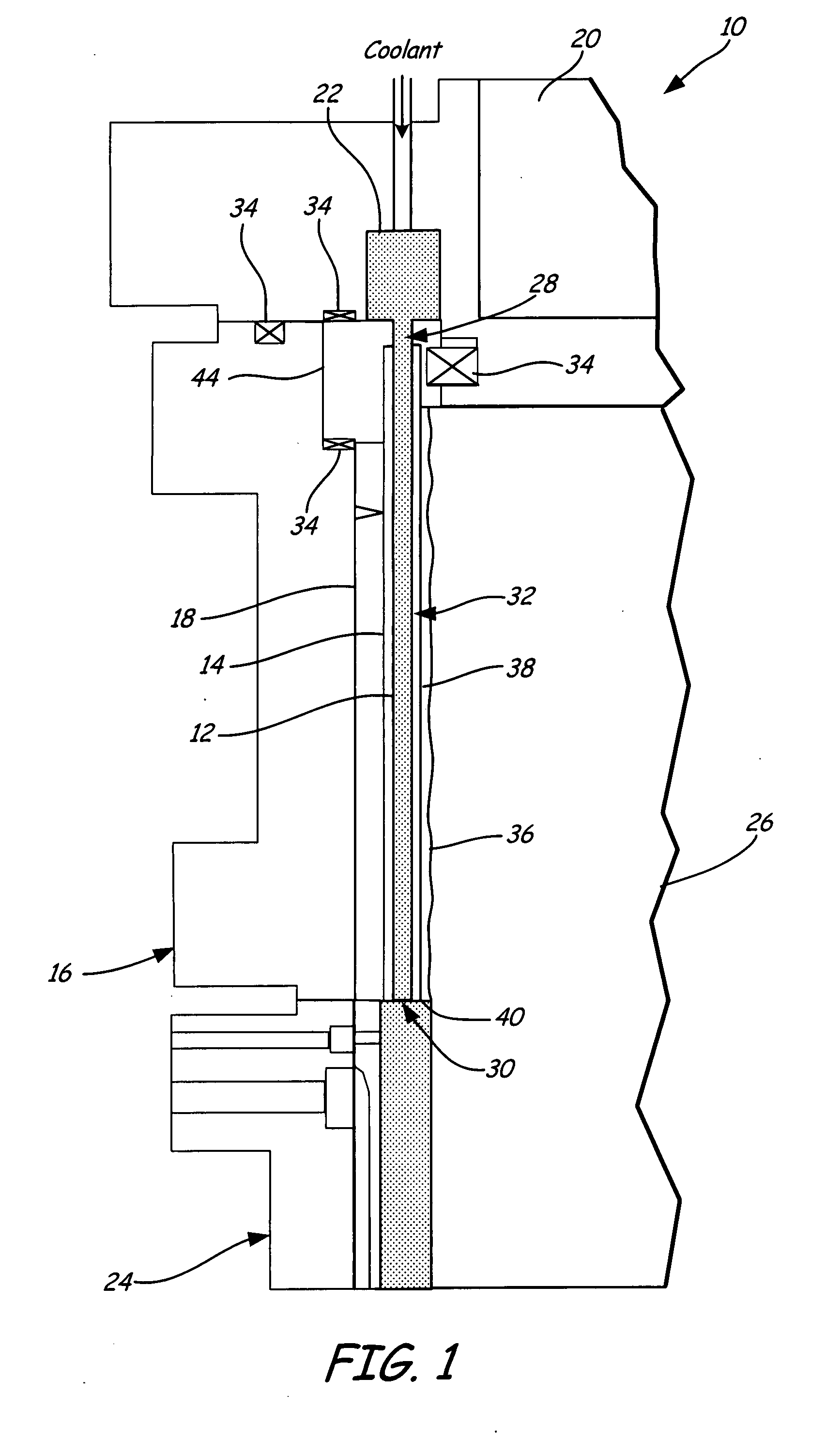
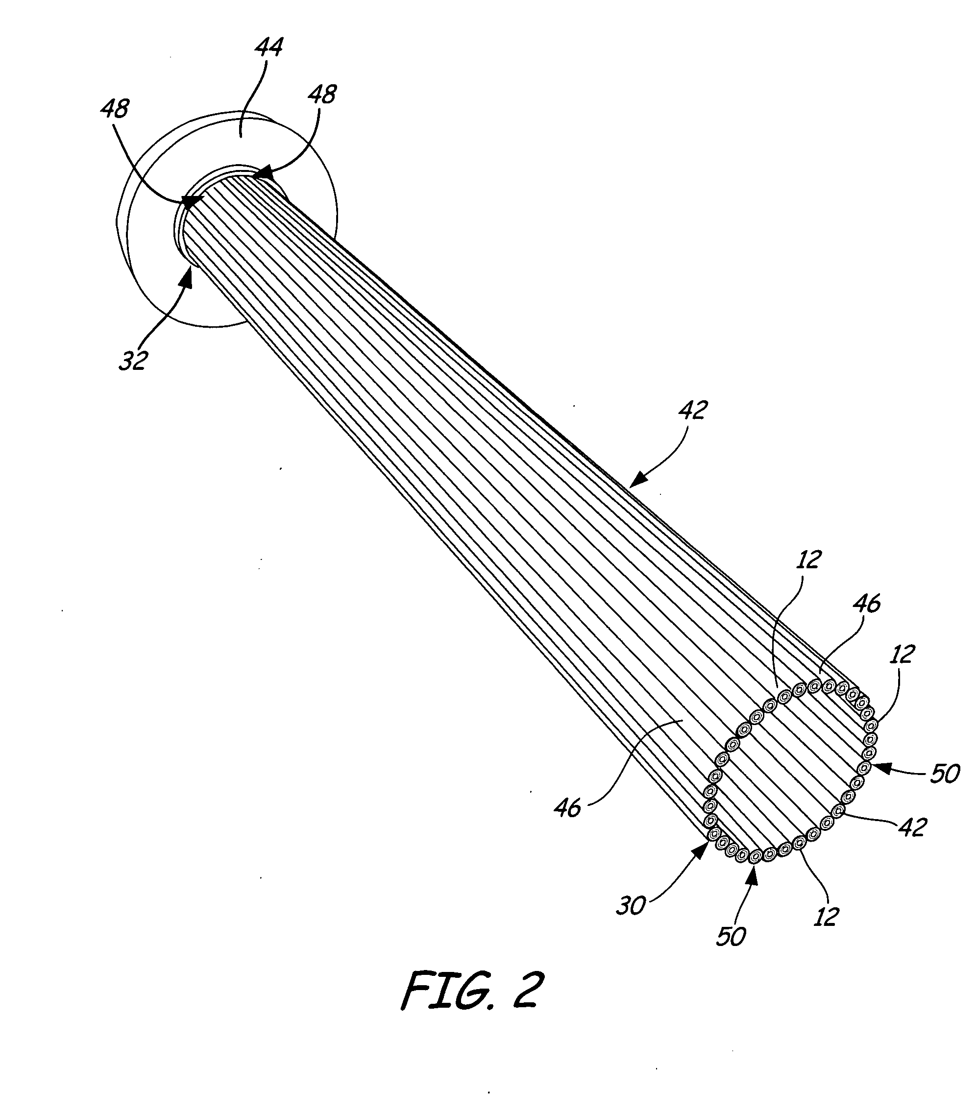
[0021]FIG. 2 shows a perspective view of coolant channels 12 and liner 42 for a dump-cooled liner configuration. As can be seen in FIG. 2, head ends 28 of coolant channels 12 are attached to injector 20 (shown in FIG. 1) by mounting flange 44, which has a circular cross-section. Thus, coolant channels 12 are positioned such that head ends 28 and aft ends 30 of all of coolant channels 12, respectively, are aligned with each other to form a circular cross-section. Liner 42 is fabricated from a plurality of sheaths 46 that are positioned over coolant channels 12. Each of sheaths 46 has a head end 48 and an aft end 50. Sheaths 46 are positioned around coolant channels 12 and have a length that is less than the length of coolant channels 12. Thus, a plurality of sheaths 46 may need to be positioned on coolant channels 12 such that coolant channels 12 are substantially covered by sheaths 46. Sheaths 46“float” on coolant channels 12, decoupling thermal expansion differences between sheaths...

second embodiment

[0025]FIG. 5 shows a partial cross-sectional view of coolant channels 12a and liner 56. Liner 56 is also formed of a plurality of sheaths 46a housing coolant channels 12a. Coolant channels 12a and sheaths 46a interact and function in the same manner as coolant channels 12 and sheaths 46 except that aft ends 30a of coolant channels 12a are flared to maintain sheaths 46a in position on coolant channels 12a without the use of tips. Accordingly, because aft ends 30a of coolant channels 12a are flared, aft ends 50a of sheaths 46a must also be flared in order to slip over aft ends 30a of coolant channels 12a. Although FIG. 5 depicts sheaths 46a as being single pieces, a plurality of sheaths 46 may be used to protect channels 12a, as long as sheaths 46a having flared aft ends 30a are positioned over flared aft ends 30a of coolant channels 12a. In addition, although FIGS. 1-5 depict coolant channels of a dump-cooled gasifier, the liners described are applicable to coolant channels having an...


PUM


Abstract

A liner for use within a gasifier vessel includes a plurality of elongated channels and a plurality of ceramic sheaths. The elongated channels pass coolant through the gasifier. The ceramic sheaths surround the elongated channels.

Description

BACKGROUND OF THE INVENTION[0001]The gasification process involves turning coal or other carbon-containing materials into synthesis gas. Because coal costs less than natural gas and oil, there is a large economic incentive to develop gasification technology. An issue with existing gasification technologies is that they generally have high capital costs and / or relatively low availability. Availability refers to the amount of time the equipment is on-line and making products. One cause of low availability is complex or short-lived gasifier liner designs. Examples of liners currently being used in gasifiers are refractory liners, membrane liners, and regeneratively cooled liners. Refractory liners require annual replacement of the refractory, with an availability of approximately 90%. While membrane liners have a longer life than refractory liners, the complexity of the liner can increase the cost of the gasifier up to 2 to 3 times.[0002]Regeneratively cooled liners are also used in th...

Claims


Application Information

Patent Timeline
IPC IPC(8): F27D1/12
CPCC10J3/485C10J3/74F27D1/12C10J2200/152F27D1/045C10J2200/09
Inventor FITZSIMMONS, MARK ANDREWYOWS, STEPHEN ARTHURFUSSELMAN, STEVEN P.
Owner GAS TECH INST
Learn More