
Method and apparatus for controlling light emitting diode

Inactive Publication Date: 2008-07-31
FREESCALE SEMICON INC
View PDF6 Cites 79 Cited by
  • Summary
  • Abstract
  • Description
  • Claims
  • Application Information

AI Technical Summary

Problems solved by technology

This “binning” requirement is expensive to implement, especially in larger BLU, for example those used in large LCD TV screens.

Method used


Image

  • Method and apparatus for controlling light emitting diode
  • Method and apparatus for controlling light emitting diode
  • Method and apparatus for controlling light emitting diode

Examples


Embodiment Construction

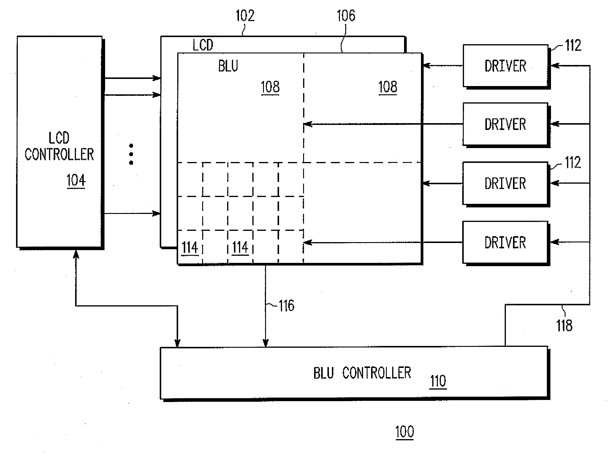
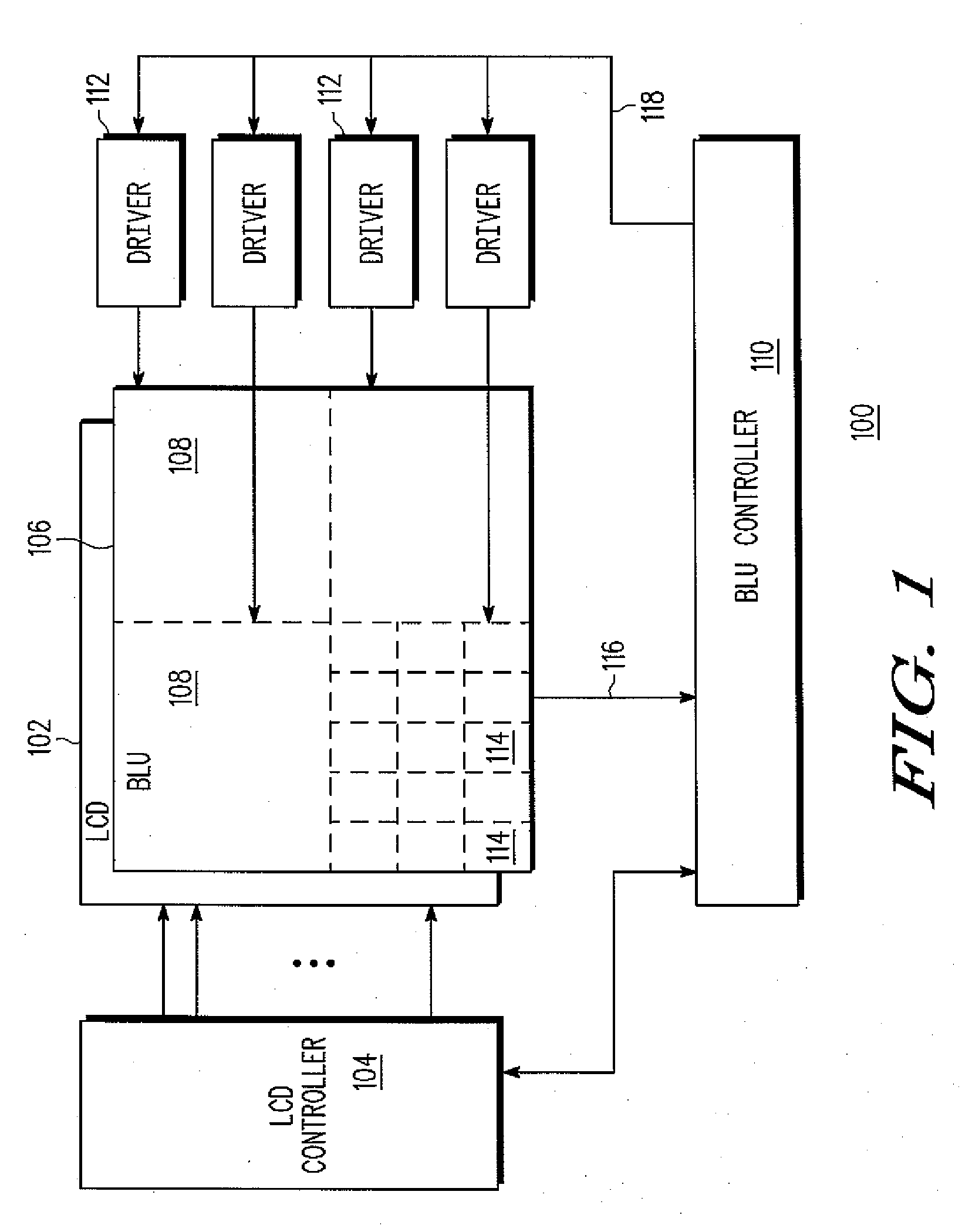
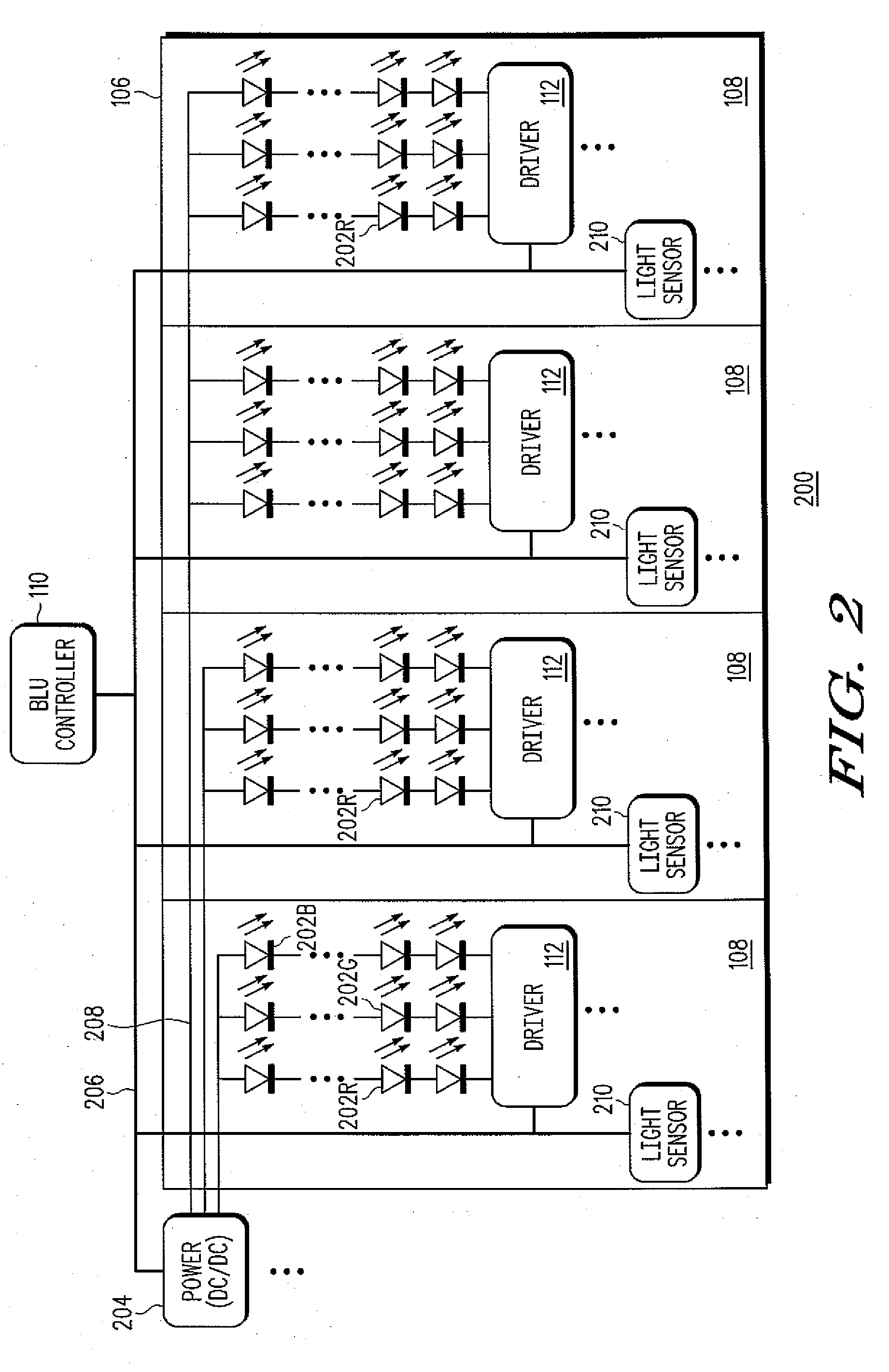
[0011]In general terms in one aspect, the present invention provides a driver architecture for driving an array of (e.g., red, blue, green, or white) LEDs, the array of LEDs being arranged into a plurality of regional arrays of LEDs having one or more common LED operational parameters such as the same bin values for color, brightness, and / or forward voltage. The driver is arranged to determine a driving signal parameter for each regional array of LEDs, and which typically corresponds to the duty cycle of a PWM signal required to illuminate the LEDs to a nominal wanted brightness level. The driving signal parameter for each region may be different in order to implement regional dimming for example; or they may be the same in order to implement a uniform brightness across the LED array. The driver also determines an operational parameter such as a bin value (e.g., color, brightness, and / or forward voltage) or bin value correction co-efficient for the LEDs of each regional array. The d...


PUM


Abstract

A method of driving an LED includes determining an operational parameter of the LED, determining a driving signal parameter for the LED, and generating a periodic driving signal for driving the LED. The generated periodic driving signal has a duty cycle that depends on the determined driving signal parameter and the determined operational parameter of the LED.

Description

BACKGROUND OF THE INVENTION[0001]The present invention relates to the field of illumination control, and in particular to the control of light emitting diodes.[0002]Arrays of LEDs are increasingly employed in backlighting units (BLU) for liquid crystal displays (LCD) installed in consumer devices ranging in size from mobile phone displays to large TV screens. Whilst LEDs can provide greater control, longer life, and uniformity of light output, the LEDs used in the BLU must be tightly specified in terms of their color, brightness, forward voltage and other characteristics. These characteristics are typically specified in terms of bin values, each bin value for an LED including a limited range of characteristic values such as wavelengths, lumen, or voltages for example. Typically the BLU will be comprised of three arrays of Red, Blue, and Green LEDs, the outputs of which are mixed to generate white light for backlighting the LCD. In order to ensure uniform brightness and efficient Ope...

Claims


Application Information

Patent Timeline
IPC IPC(8): G06F3/038G09G3/32
CPCG09G3/3413G09G3/3426G09G2360/145G09G2320/064G09G2320/0686G09G2320/041
Inventor FUNG, KAI MINGLAU, CHIN TUNG DEREKLI, CHE CHUNG ROYLUI, CHONG YIU DENNIS
Owner FREESCALE SEMICON INC
Learn More