
Foundation lifting assembly and method of use

a technology for supporting and structural buildings, applied in foundation engineering, bulkheads/piles, construction, etc., can solve the problems of affecting structural integrity, less suitable for new construction, and affecting the stability of the structur

Inactive Publication Date: 2008-07-24
ROBERTS WILSON D +1
View PDF2 Cites 21 Cited by
  • Summary
  • Abstract
  • Description
  • Claims
  • Application Information

AI Technical Summary

Benefits of technology

[0007]Accordingly, there is provided herein, a lifting assembly (and method of use) that, in its preferred embodiments, is capable of raising, stabilizing, and supporting a structural foundation such that a portion of said assembly is integrally attached to said foundation.
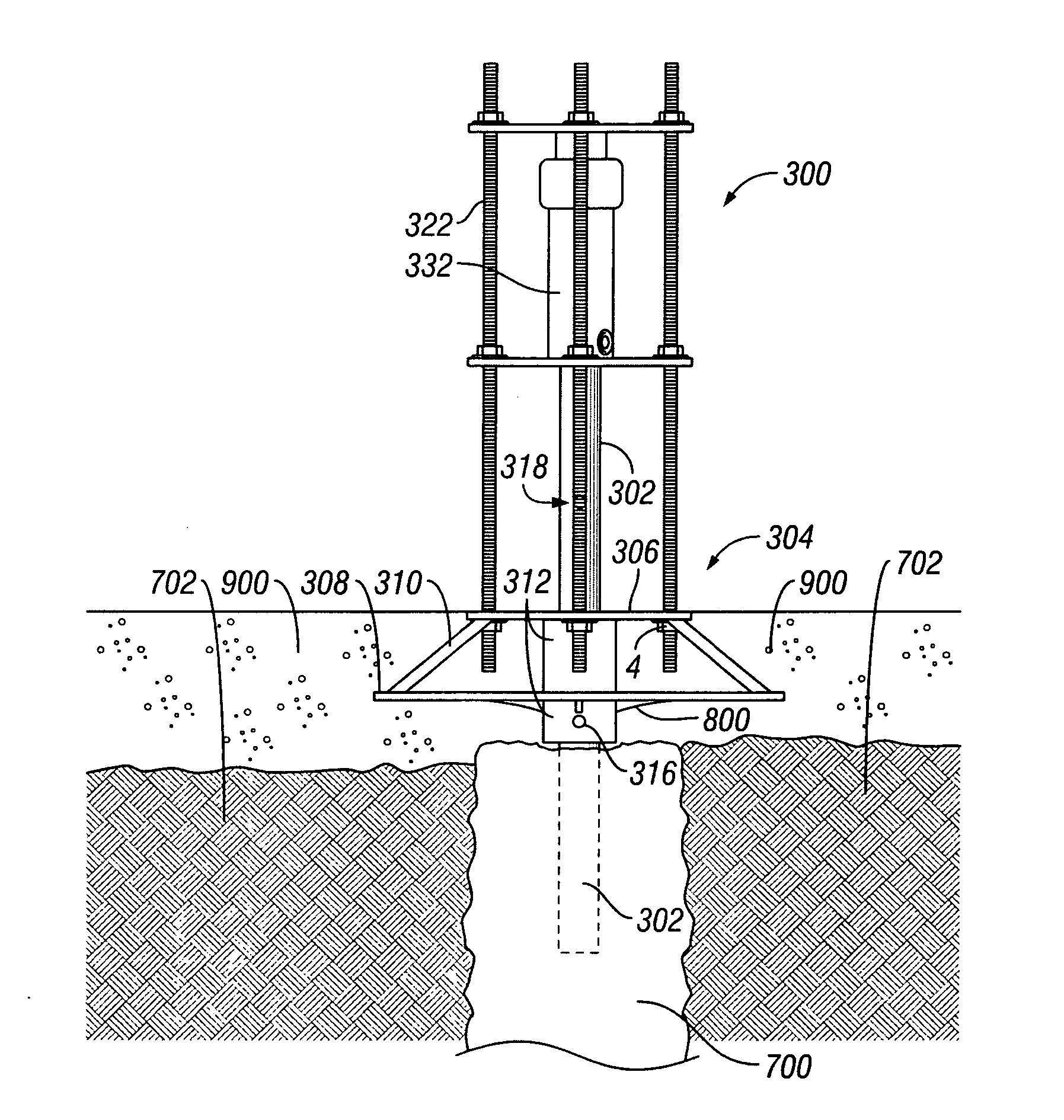
[0009]In another aspect of the invention, each of a plurality of holes which have been formed on the upper support structure of the anchoring bracket, receive a threaded rod which is secured thereto by a nut on the underside of said upper support structure. A jacking assembly, comprising a bottom plate, top plate, and a hydraulic jack, is configured to lift the anchoring bracket. The bottom plate is removably mounted on the top end of the vertical support column, thus providing a stable support for the lifting means, which is positioned between the bottom plate and top plate. The support rods which are secured to the anchoring bracket, extend through holes formed in each of the top and bottom plates. Nuts are fastened to support rods on the upper part of each of the top and bottom plates.

Problems solved by technology

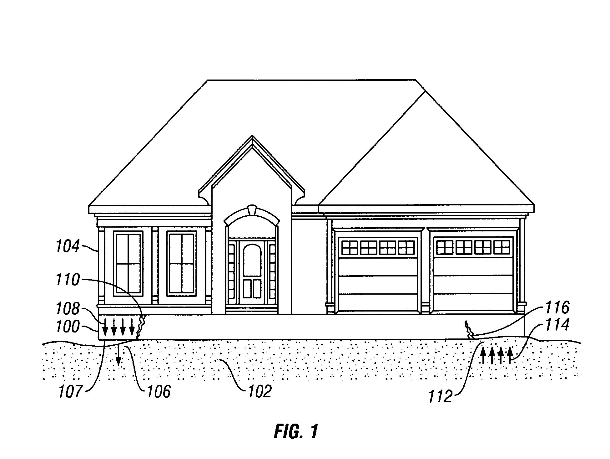
Fractures in a foundation can severely affect the structural integrity of the house or other building supported by said foundation, or at the very least, require the owner of such a structure to expend a substantial amount of money in order to remedy the problem.
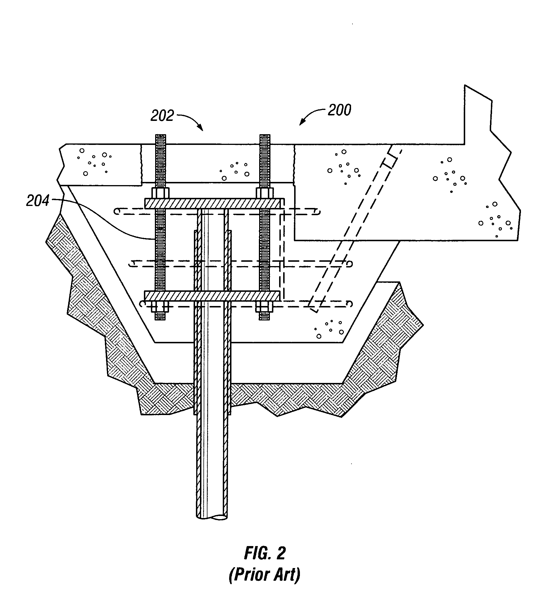
A drawback of the assembly disclosed in the Rupiper patent is that while it is suitable for lifting a preexisting foundation, it is less suitable for use in construction of new structures as the pierhead is not integral to the foundation.

Method used


Image

  • Foundation lifting assembly and method of use
  • Foundation lifting assembly and method of use
  • Foundation lifting assembly and method of use

Examples


Embodiment Construction

[0034]Referring to FIG. 3, a perspective view of a preferred embodiment of the lifting assembly 300 of the present invention. The lifting assembly is mounted on a vertical support column 302 which has been embedded within the ground at a location where the lifting assembly 300 is to support a structural foundation or other weighted member. An anchoring bracket 304, comprises an upper support structure 306, a lower support structure 308, upper support members 310, lower support members (not shown), and a sleeve 312. The anchoring bracket 304 is mounted to the vertical support column 302 such that said support column 302 extends through the sleeve 312. Although the sleeve 312 fits securely around the support column 302, the sleeve 312 must be sized in such a manner as to allow the anchoring bracket 304 to slide upwards and downwards along the exposed vertical column 302. However, it is contemplated that lubricants may be used to increase the anchoring bracket's 304 ability to slide al...


PUM


Abstract

A lifting assembly for raising, supporting, and stabilizing a foundation or other weighted member. An anchoring bracket, which is mounted to a piling or pier that has been driven into the ground below the location where the foundation is to be poured, is attached to a jacking assembly. The jacking assembly includes a bottom plate which rests on the upper end of the vertical support column, a hydraulic jack which rests on the bottom plate, and a top plate which is supported by the hydraulic jack. Concrete which will form the foundation is poured into the foundation mold and around the anchoring bracket which rests in said mold. The concrete foundation is allowed to cure. Support rods which are secured to the anchoring bracket and bottom and top plates, transfers the upward force generated by the hydraulic lift, from said top plate to said anchoring bracket, thus lifting the foundation to which the anchoring bracket is integrally attached.

Description

CROSS-REFERENCE TO RELATED APPLICATION[0001]This application claims the benefit of and priority to a U.S. Provisional Patent Application No. ______ filed ______, the technical disclosure of which is hereby incorporated herein by reference.FIELD OF THE INVENTION[0002]The present invention relates generally to an assembly and method for lifting supporting, and stabilizing structural building foundations and more particularly, to an assembly having an anchoring portion integrally attached to said foundation which is lifted, relative to a support column, by a jacking portion of said assembly such that said foundation is lifted off the ground.DESCRIPTION OF THE RELATED ART[0003]When the construction of a structure such as a house or other building is set to commence, particular attention must be paid to the stability of the ground upon which the structure will be built. The foundation of the structure must rest on stable, level ground in order to prevent damage to the foundation, and ver...

Claims


Application Information

Patent Timeline
IPC IPC(8): E02D5/10
CPCE02D35/00
Inventor ROBERTS, WILSON D.FULLER, TRENT D.
Owner ROBERTS WILSON D
Learn More