
Specular reflection reduction using multiple cameras

Inactive Publication Date: 2008-07-10
MICROSOFT TECH LICENSING LLC
View PDF23 Cites 31 Cited by
  • Summary
  • Abstract
  • Description
  • Claims
  • Application Information

AI Technical Summary

Benefits of technology

[0005]Although not required, embodiments of the present invention relate to an interactive display system that includes an interactive display screen. An illuminator is positioned to illuminate one of the inner or outer surfaces of the display screen. At least two cameras are placed so as to view the il

Problems solved by technology

The specular reflection may be so strong that it would be difficult to distinguish any image actually reflected from an input object within the area of the specular reflection.
Accordingly, specular reflections can adversely impact the ability to use an interactive display as input, especially if the input object is positioned at an area of the display screen in which the camera is experiencing a specular reflection.

Method used


Image

  • Specular reflection reduction using multiple cameras
  • Specular reflection reduction using multiple cameras
  • Specular reflection reduction using multiple cameras

Examples


Embodiment Construction

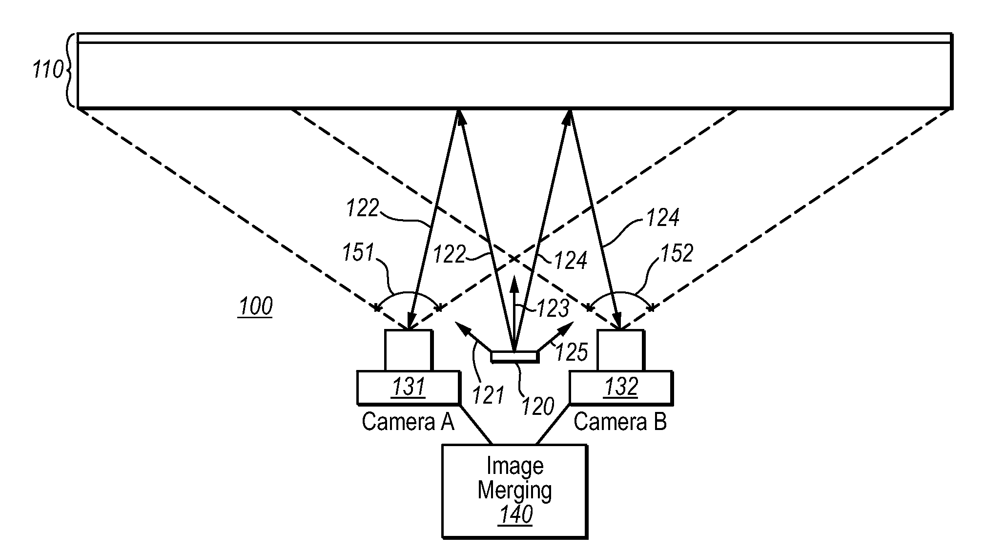
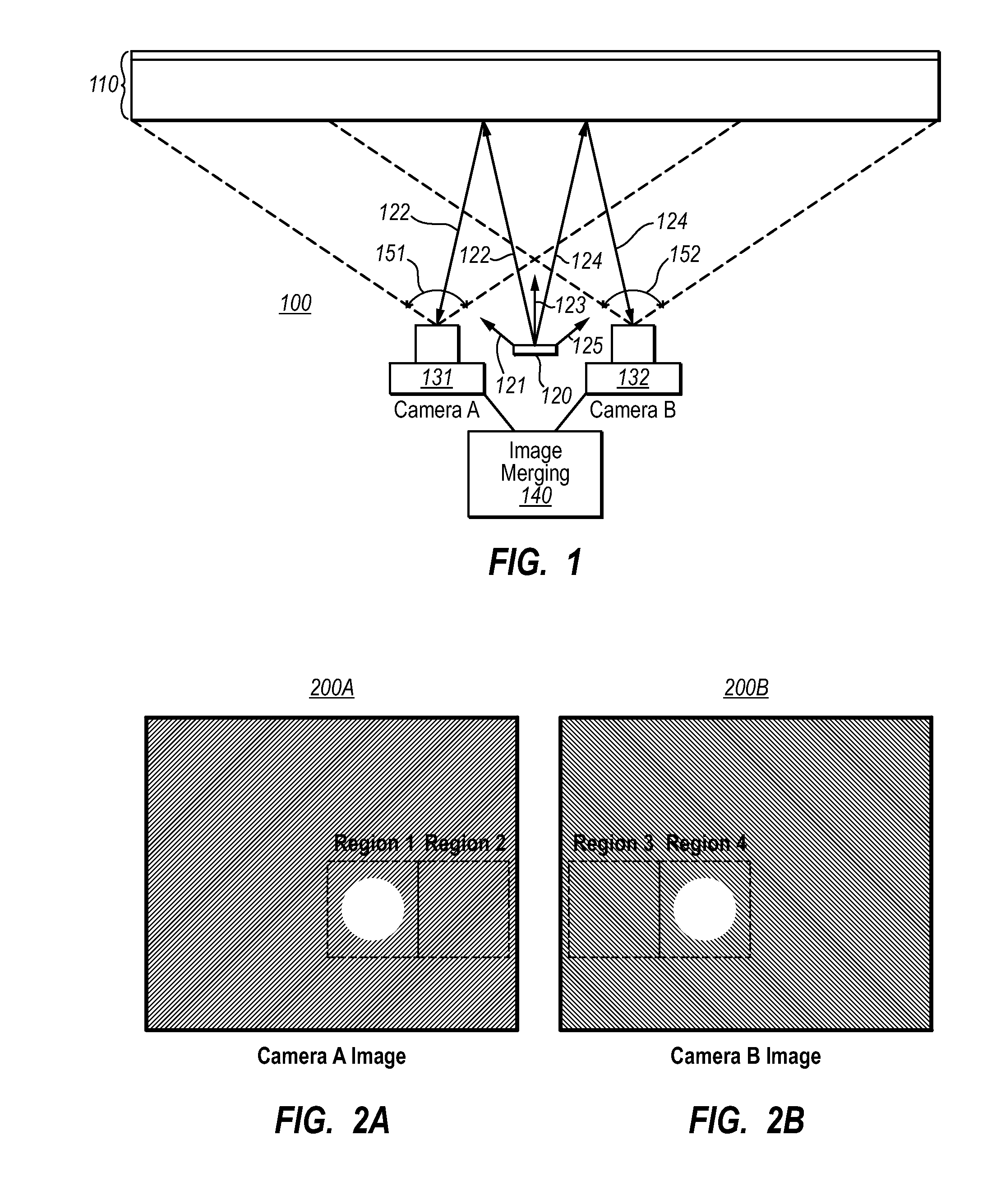
[0015]Embodiments of the present invention extend to an interactive display that includes multiple cameras placed so as to have a view of the inside or outside surfaces of the display screen. An illuminator is also placed to illuminate the viewed display screen surface so that reflected images of objects in front of or in contact with the display screen can be received by the cameras. The areas of specular reflection are different for at least two of the cameras, such that images from one of the cameras can be used to reduce or cancel specular reflection from the other camera.

[0016]FIG. 1 illustrates a side-view of an interactive display 100 in accordance with one embodiment of the present invention. The interactive display 100 is configured to display images from the outer surface (the top surface as illustrated in FIG. 1) of one or more transparent or semi-transparent layers comprising the display screen 110. However, separate and apart from the display mechanism, which is largely...


PUM


Abstract

An interactive display system that includes an interactive display screen. An illuminator is positioned to illuminate one of the inner or outer surfaces of the display screen. At least two cameras are placed so as to view the illuminated surface of the display screen. Each of at least one of the cameras are positioned such that specular reflections from the illuminator are received by the camera. The images from the different cameras are merged to form a merged image in which specular reflections are reduced or even cancelled.

Description

BACKGROUND[0001]The functionality of many computing systems and other devices relies on effective display of information using a display. More recently, the display has also been used in an interactive manner as a direct user input device. For instance, a display might be equipped with touch sensitive resistive and / or capacitive arrays to detect a portion of the display screen being physically contacted.[0002]Some conventional interactive displays use “vision capture” technology in which a camera is positioned behind the display screen, the display screen composed of one or more layers of transparent or semitransparent material. An infrared illuminator is also positioned behind the display screen to illuminate an object in front of or in contact with the display. Illumination light (i.e., light originating from the illuminator) reflected from the object is received by the camera, which takes a picture of the reflected light. The picture is used as an electronic input to the system. ...

Claims


Application Information

Patent Timeline
IPC IPC(8): H04N5/222G06K9/36G06F3/033G06F3/0346G06F3/041
CPCG06F3/0425G06F3/0418G06F3/04182H04N5/262H04N13/00
Inventor JENKINS, DAVID R.
Owner MICROSOFT TECH LICENSING LLC
Learn More