
Rear aperture sight for rifle

a rear aperture and rifle technology, applied in the field of rifle sighting systems, can solve the problems of limited light passing through the opening, hindering the accuracy of aiming ability and hence the accuracy of shot placement, and less light being permitted to pass through the opening

Inactive Publication Date: 2008-07-10
NEERGAARD ARTHUR
View PDF23 Cites 0 Cited by
  • Summary
  • Abstract
  • Description
  • Claims
  • Application Information

AI Technical Summary

Benefits of technology

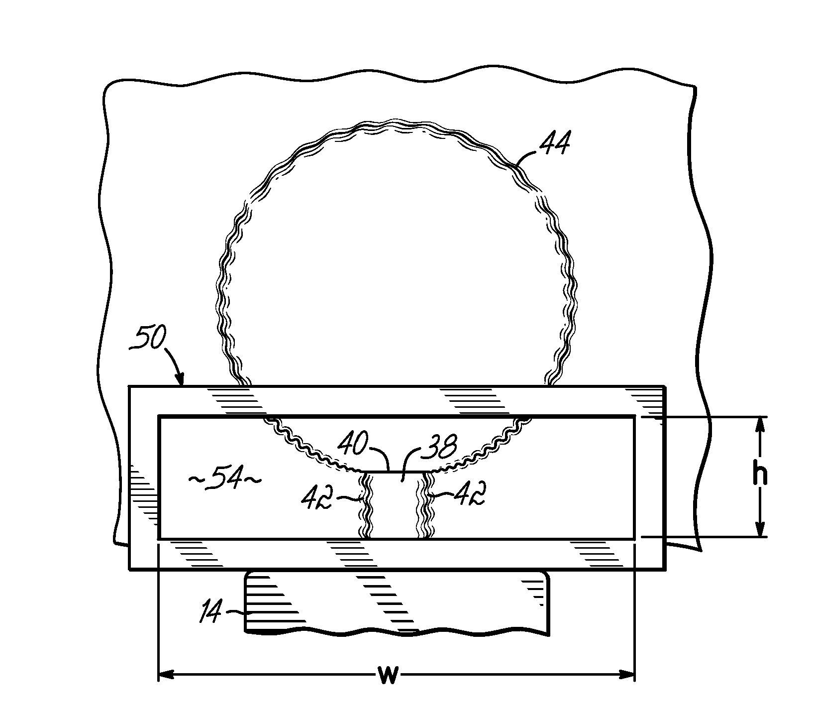
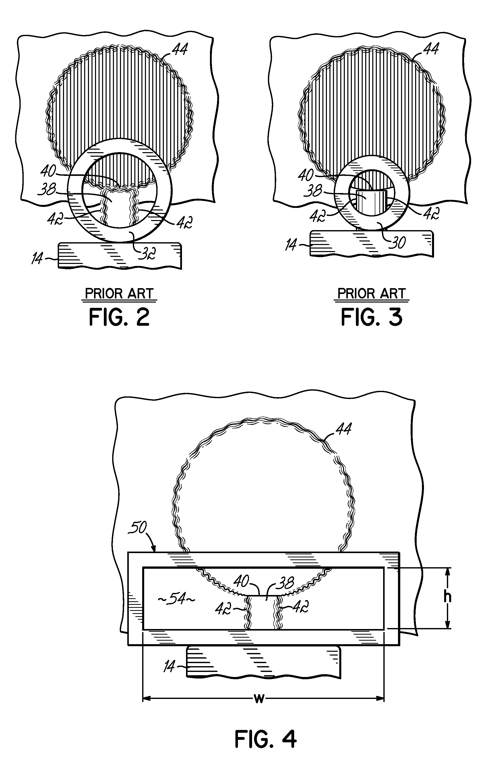
[0009]In one aspect, the present invention is a rear aperture sight for use in conjunction with a front sight post sight on a rifle, the front sight post having a horizontal top edge and vertical side edges. The rear aperture sight comprises a rear sight adapted to be mounted on the rifle. The rear sight has a horizontally elongated aperture formed therein having height and width dimensions. The width dimension is greater than the height dimension. The height dimension is of such a value that the aperture is adapted to cause the horizontal top edge of the front sight post and a horizontal edge of a target to be sharply focused. The width dimension is of such a value that the aperture is adapted to permit a sufficient amount of light to pass through the aperture so that the front sight post and the target are bright.
[0013]The invention thus provides a rear aperture sight for a rifle which sharply focuses the horizontal top edge of the front sight post and the horizontal bottom edge of the target, while at the same time permitting sufficient light to pass therethrough so that the front sight post and target are bright.

Problems solved by technology

A distinct disadvantage in using the smaller rear circular aperture is that less light is permitted to pass through the aperture.
Thus, even though the horizontal top edge and vertical side edges of the front sight post and target are clearly focused which enhances accuracy in aiming and hence accuracy in shot placement, the front sight post and target are nevertheless dim, which hinders accuracy in aiming ability and hence accuracy in shot placement.
A problem with traditional round aperture sights is that once the aperture is reduced in size to provide optimal focus on the horizontal top edge of the front sight post and the horizontal bottom edge of the target, the amount of light passing through the opening is so limited that the target and the front sight post appear dim to the shooter.

Method used


Image

  • Rear aperture sight for rifle
  • Rear aperture sight for rifle
  • Rear aperture sight for rifle

Examples


Embodiment Construction

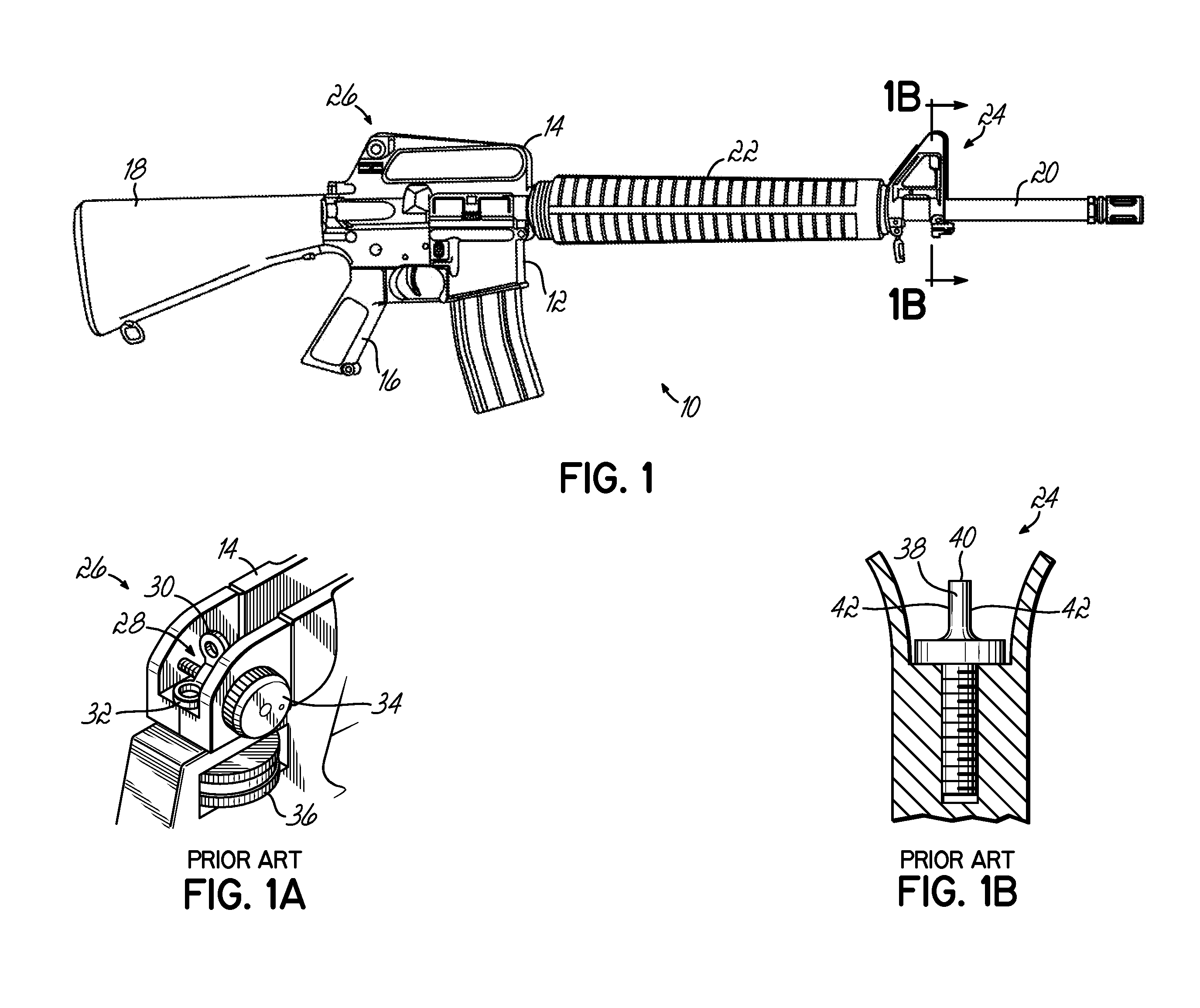
[0022]Referring first to FIG. 1, there is illustrated the United States military M16A2 service rifle 10, comprising, generally, lower receiver 12, upper receiver 14, pistol grip 16, buttstock 18, barrel 20, handguard 22, front sight assembly 24 and rear sight assembly 26. FIG. 1A shows the prior art rear sight assembly 26 in more detail. It comprises a flip type dual leaf sight 28 having a smaller aperture 30 having a diameter of about 0.070 inch for longer ranges, and a larger aperture 32 having a diameter of about 0.2 inch for shorter ranges. A windage knob 34 is used to adjust the windage of the rear sight assembly 26. An elevation knob 36 is used to adjust the elevation of the rear sight assembly 26 for ranges beyond 300 meters. FIG. 1B shows the prior art front sight assembly 26 in more detail. It comprises a post 38 which is adjustable but which is only used to initially zero the rifle. (As used herein, the term “post” shall be deemed to embrace any front sight aiming device, ...


PUM


Abstract

A rear aperture sight for use in conjunction with a front sight post sight on a rifle. The front sight post has a horizontal top edge and vertical side edges. The rear aperture sight comprises a rear sight adapted to be mounted on the rifle. The rear sight has a horizontally elongated aperture formed therein having height and width dimensions. The width dimension is greater than the height dimension. The height dimension is of such a value that the aperture is adapted to cause the horizontal top edge of the front sight post and a horizontal edge of a target to be sharply focused. The width dimension is of such a value that the aperture is adapted to permit a sufficient amount of light to pass through the aperture so that the front sight post and the target are bright.

Description

FIELD OF THE INVENTION[0001]This invention relates generally to firearms, and more particularly to sighting systems for firearms.BACKGROUND OF THE INVENTION[0002]The United States military issues for service a pair of shoulder fired small arms both chambered for the 5.56 mm NATO cartridge. One is designated the M16A2 / M16A3 / M16A4 rifle and the other is designated the M4 / M4A1 carbine. Both weapons utilize a common sighting system comprising a rear sight having a leaf with a circular aperture therein and a front sight post. To properly aim the weapon, the horizontal top edge of the front sight post is centered horizontally and vertically on the target, and is also centered in the rear aperture.[0003]Both weapons utilize a rear flip type dual leaf sight having two different aperture sizes from which to choose: a smaller aperture having a diameter of about 0.070 inch for longer ranges, and a larger aperture having a diameter of about 0.2 inch for shorter ranges, a greater field of view, ...

Claims


Application Information

Patent Timeline
IPC IPC(8): F41G1/00
CPCF41G1/08
Inventor NEERGAARD, ARTHUR
Owner NEERGAARD ARTHUR
Learn More