Fully-differential amplifier
a technology of amplifiers and differential amplifiers, applied in the direction of differential amplifiers, amplifiers with semiconductor devices/discharge tubes, dc-amplifiers with dc-coupled stages, etc., can solve the problems of unstable feedback loop of common-mode signals and the possibility of using conventional circuits, and achieve small power consumption and sufficient gain
- Summary
- Abstract
- Description
- Claims
- Application Information
AI Technical Summary
Benefits of technology
Problems solved by technology
Method used
Image
Examples
first embodiment
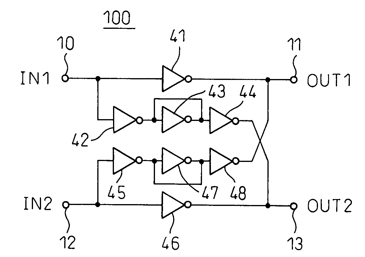
[0058]FIG. 6 is a circuit diagram showing the configuration of a fully-differential amplifier 100 canceling out an input side common-mode signal by a feedforward operation according to the present invention. As shown in the figure, this fully-differential amplifier 100 is a fully-differential amplifier which amplifies and inverts the voltage difference of the first and second input signals IN1, IN2 input to the first and second input terminals 10, 12 and outputs it as the first and second output signals OUT1, OUT2 to the first and second output terminals 11, 13. It is provided with a first inverter 41 connected between the first input terminal 10 and first output terminal 11, a second inverter 46 connected between the second input terminal 12 and second output terminal 13, a third inverter 42 with the first input terminal 10 as an input, a fourth inverter 43 with an input and output connected to the output of the third inverter and with the input and output short-circuited, a fifth ...
second embodiment
[0063]The signal voltage input from the first input terminal 10 of FIG. 7 is output by the inverter 41′ as the current amplified gm times to the first output terminal 11. At the same time, the voltage of the signal IN1 input from the first input terminal 10 is output by the inverter 42′ as the current amplified gm times to the inverter 43′ having its input and output short-circuited. The inverter 43′ has its input and output short-circuited, so operates as a 1 / gm resistor. On the other hand, the voltage of the signal IN2 input from the second input terminal 12 of FIG. 7 is output by the inverter 46′ as the current amplified gm times to the second output terminal 13. At the same time, the voltage of the signal IN2 input from the first input terminal 12 is output by the inverter 45′ as the current amplified gm times to the inverter 47′ with its input and output short-circuited. The inverter 47′ has the input and output short-circuited, so operates as a 1 / gm resistor. Here, since the i...
fourth embodiment
[0069]S. Chatterjee, Y. Tsividis, P. Kinget, “A 0.5V Filter with PLL-Based Tuning in 0.18 μm CMOS,”Digest of Technical Papers, IEEE ISSCC2005, 27.8, pp. 506-507, February 2005 and S. Chatterjee, Y. Tsividis, P. Kinget. “0.5-V Analog Circuit Techniques and Their Application in OTA and Filter Design,”IEEE Journal of Solid-State Circuits, Vol. 40, No. 12, pp. 2373-2387, December 2005 also describe fully-differential amplifiers configured to suppress the common-mode component of input signals by a feedforward operation and suppress the common-mode component of the output side by a feedback operation. These are worked in single-stage amplifiers. Two single-stage fully-differential amplifiers provided with CMFF and CMFB functions are connected in cascade to form such fully-differential amplifiers. As opposed to this, in the present invention, there is the difference that a single-stage fully-differential amplifier provided with just a CMFF and a single-stage fully-differential amplifier p...
PUM
 Abstract
Description
Claims
Application Information
 - R&D
- Intellectual Property
- Life Sciences
- Materials
- Tech Scout
- Unparalleled Data Quality
- Higher Quality Content
- 60% Fewer Hallucinations
Browse by: Latest US Patents, China's latest patents, Technical Efficacy Thesaurus, Application Domain, Technology Topic, Popular Technical Reports.
© 2025 PatSnap. All rights reserved.Legal|Privacy policy|Modern Slavery Act Transparency Statement|Sitemap|About US| Contact US: help@patsnap.com


