System and method for merging images of an object
- Summary
- Abstract
- Description
- Claims
- Application Information
AI Technical Summary
Benefits of technology
Problems solved by technology
Method used
Image

Examples
Embodiment Construction
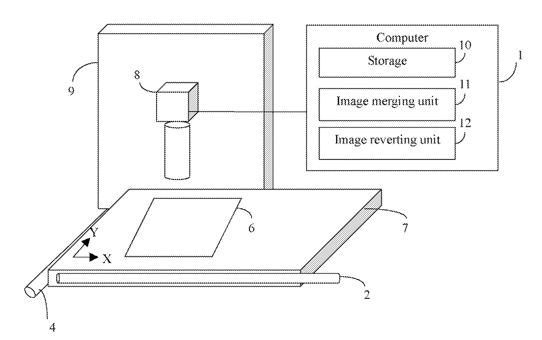
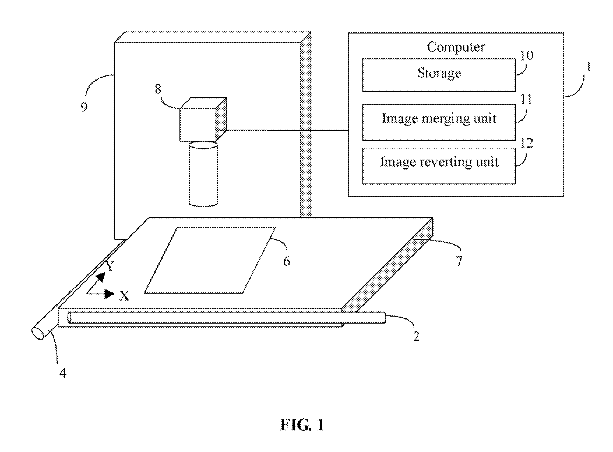
[0018]FIG. 1 is a schematic diagram of a system for merging images of an object 6 (hereinafter, “the system”) in accordance with a preferred embodiment. The system includes a computer 1 configured to measure an object 6 fixed at a platform 7 of a measuring machine 9. The computer 1 mainly includes a storage 10, an image merging unit 11, and an image reverting unit 12. A charged coupled device (CCD) 8 fixed at a Z-axis of the measuring machine 9 capturing a series of images of the object 6, and records coordinate values of center points of the images when capturing the images. The CCD 8 includes an optical lens that focuses on the object 6 for capturing the series of the images of different parts of the object 6.
[0019]The measuring machine 9 includes an X-axis manual rocker 2, a Y-axis manual rocker 4, and a Z-axis manual rocker (not shown). The X-axis manual rocker 2 may control the platform 7 to move in the direction of left and right. The Y-axis manual rocker 4 may control the pla...
PUM
 Abstract
Description
Claims
Application Information
 - R&D
- Intellectual Property
- Life Sciences
- Materials
- Tech Scout
- Unparalleled Data Quality
- Higher Quality Content
- 60% Fewer Hallucinations
Browse by: Latest US Patents, China's latest patents, Technical Efficacy Thesaurus, Application Domain, Technology Topic, Popular Technical Reports.
© 2025 PatSnap. All rights reserved.Legal|Privacy policy|Modern Slavery Act Transparency Statement|Sitemap|About US| Contact US: help@patsnap.com