
Jewelry organizer

a technology for organizing and jewelry, applied in the field of jewelry organizers, can solve the problems of difficult to insert and remove jewelry from the stands, the jewelry cannot be placed on the horizontal surface without falling, and the jewelry is located inside the container

Inactive Publication Date: 2008-06-05
FOR YOUR EASE ONLY
View PDF92 Cites 34 Cited by
  • Summary
  • Abstract
  • Description
  • Claims
  • Application Information

AI Technical Summary

Benefits of technology

"The present invention relates to a jewelry organizer with unique slidable features. The technical effects of this invention include easy access to jewelry, convenient viewing and selection of jewelry, and effective storage and organization of jewelry. The organizer has a top section, middle section, and bottom section, with slidable features that allow for easy access to jewelry and easy cleaning. The organizer can hold a large amount of jewelry in an organized fashion that allows for direct and easy access to the jewelry. The organizer also makes visual inspection of the items contained therein easy and groups like items together."

Problems solved by technology

A particular problem with this type of jewelry holder is that it is very difficult to insert and remove the jewelry from the stands because the side walls and hinged top limit the amount of space available.
Again, a problem with this type of jewelry holder is that because the racks are designed as an integral part of the box-like container when the racks are removed from the container, the racks cannot be placed on a horizontal surface without falling over.
In addition, because there is only one open side, access to the jewelry located inside the container is limited.

Method used


Image

  • Jewelry organizer
  • Jewelry organizer
  • Jewelry organizer

Examples


Embodiment Construction

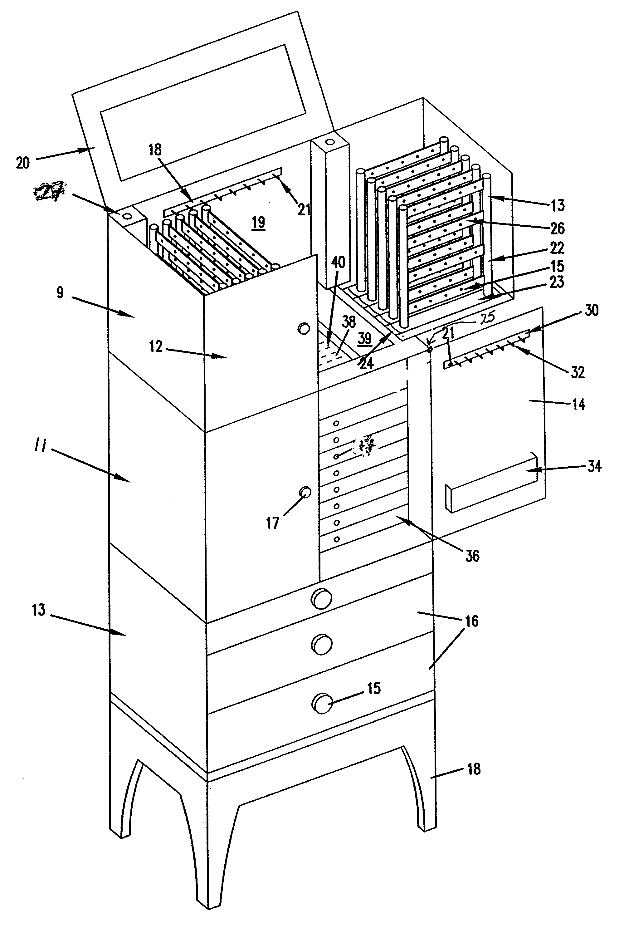
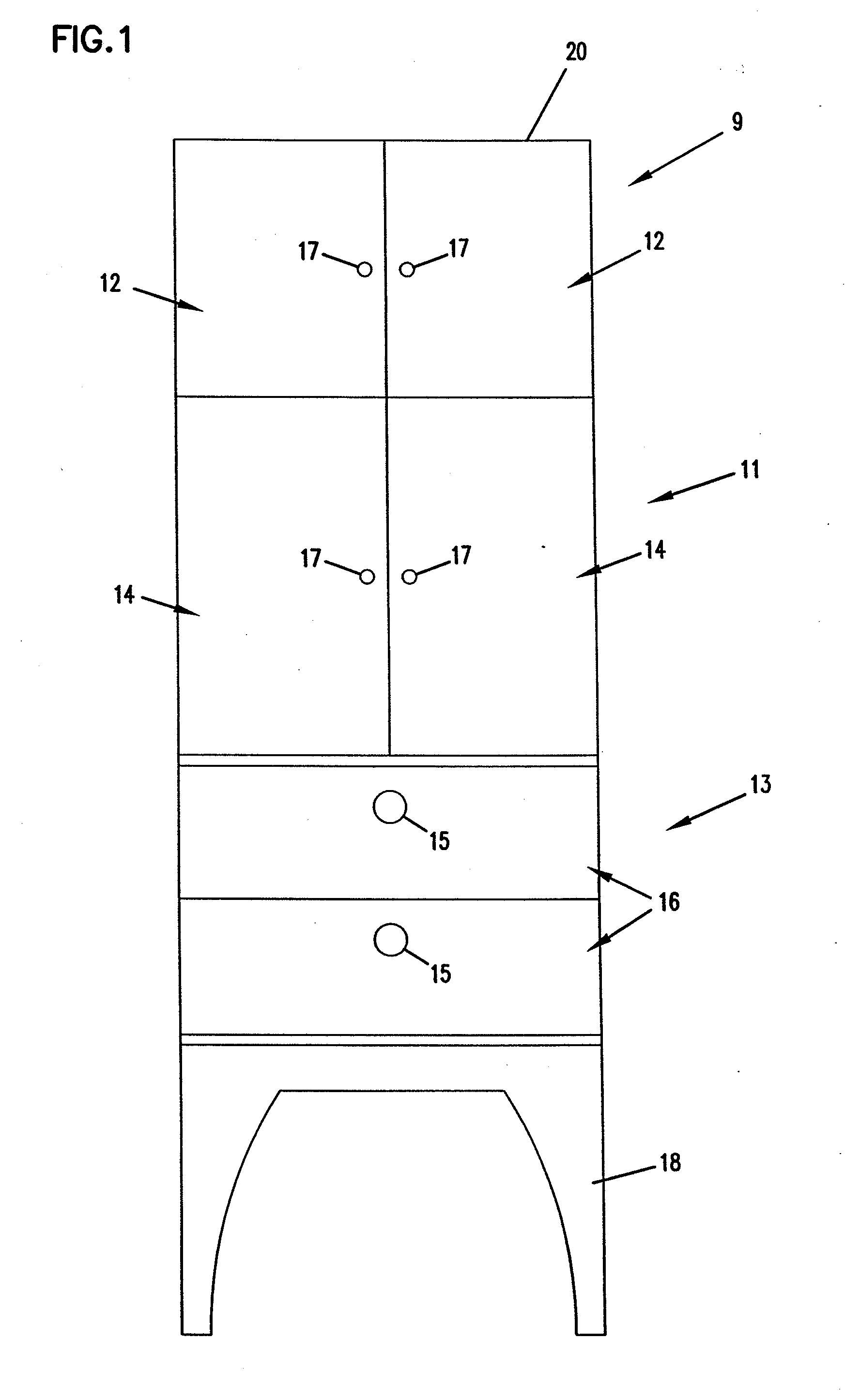
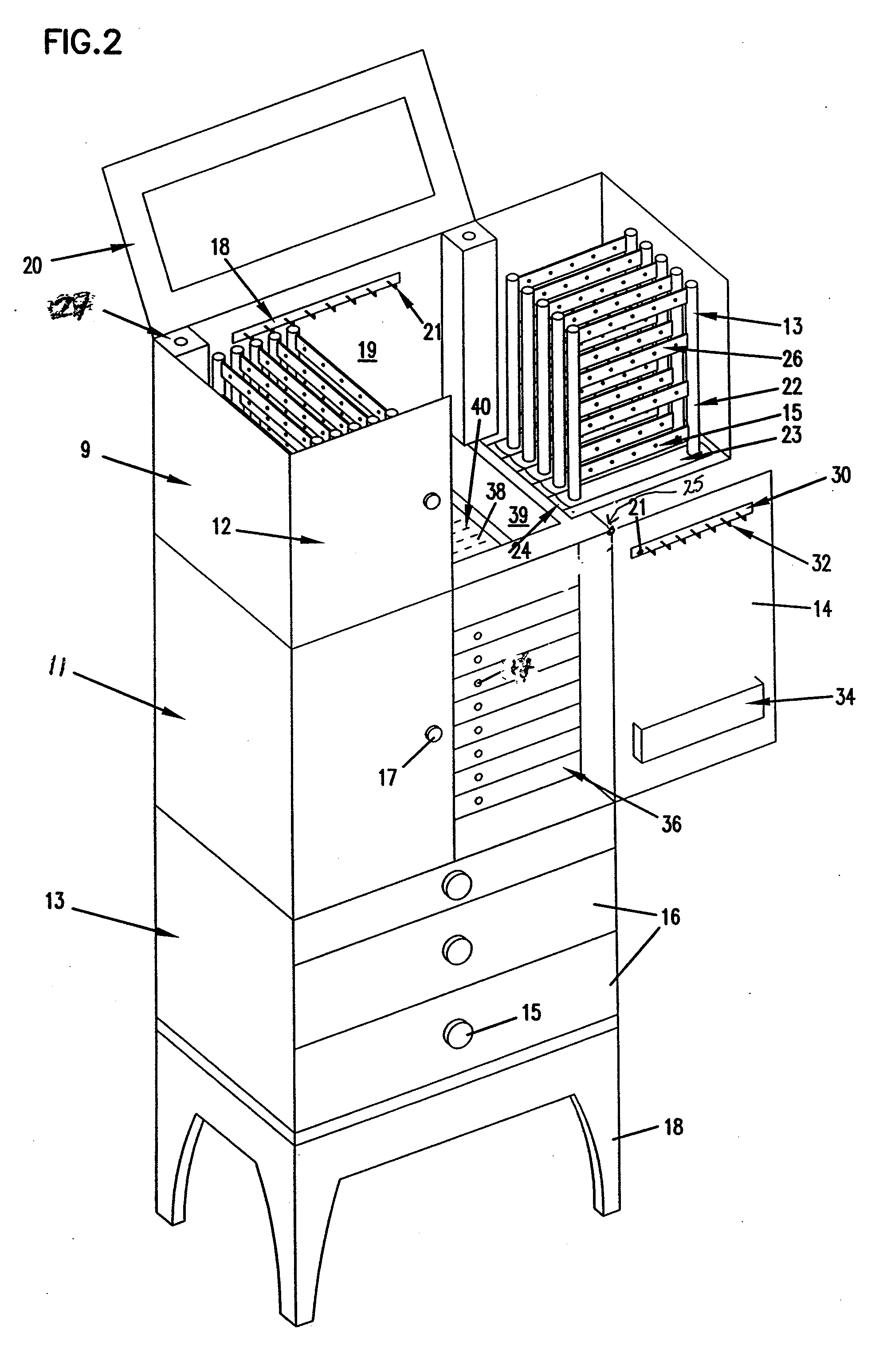
[0027]FIG. 1 is a front elevational view of a jewelry organizer according to a first preferred embodiment of the invention. The jewelry organizer 10 has a top section 9, a middle section 11 and a bottom section 13. The top section 9 includes two doors 12. The middle section 11 includes two mid-level doors 14 and the bottom section 13 includes a plurality of drawers 16. While there are only two drawers 16 illustrated in the bottom section 13, there may be more or less and the present invention is not limited to the particular embodiments illustrated. The bottom section 13 may include legs 18 as shown or, alternatively, the bottom section 13 of the organizer 10 may be a chest of drawers that extend to the floor. The organizer 10 has a lid 20 that can be pivoted open to expose a mirror as will be described hereinafter. Pull handles 15 and / or knobs 17 are included on the drawers 16 and / or doors 12, 14 respectively. In a preferred embodiment, the top, middle and bottom sections 9-13 are ...


PUM


Abstract

A jewelry organizer for storing jewelry having a plurality of compartments to store jewelry items of various configurations. The jewelry organizer includes pivoting cabinets having earring stands that are slidably received in the cabinets. Drawers are located under the cabinets and have various compartments to hold jewelry items such as bracelets, rings and pins. A pair of doors flanks the drawers and may conceal the drawers when the pair of doors are closed.

Description

RELATED APPLICATION[0001]The present application is related to U.S. patent application Ser. No. 09 / 728,505, entitled “Jewelry Chest and Box with Slidable Features” filed Dec. 1, 2000, incorporated herein by reference.FIELD OF THE INVENTION[0002]The present invention relates to a jewelry organizer with unique slidable features. While several different types of jewelry organizers are known, there is a need for a jewelry organizer that is convenient to use and allows a user to easily view and select jewelry.BACKGROUND OF THE INVENTION[0003]One type of a known jewelry holder is in the form of a container with relatively high sides and back walls and a top that is hinged to the back wall to permit access into the container. Earring stands are fixed to the bottom of the container. A particular problem with this type of jewelry holder is that it is very difficult to insert and remove the jewelry from the stands because the side walls and hinged top limit the amount of space available.[0004...

Claims


Application Information

Patent Timeline
Patent Type & Authority Applications(United States)
IPC IPC(8): A47B88/20A45C11/16A47B83/00A47B67/00A47B46/00A47F7/02
CPCA47B45/00A47F7/02A47B81/00A47B46/00
Inventor GREINER, LORI
Owner FOR YOUR EASE ONLY
Learn More